
Three Axis Gimbal Repair & Optimization
There is a certain thrill in finding useful electronics discarded in ewaste bins. Sure, most of the time its either an old broken tank of a laser printer or a very-used microwave, but those few times when you find something you've been holding off on purchasing - those are priceless. This was one of them. I had been eyeing some form of portable video stabilizing equipment ever since the infamous 2013 NAB release of the Freefly Movi. Sure, the mangled up gimbal I found was far from a Movi, but that shoddy piece of equipment would finally allow me to stabilize my mirrorless camera footage. It just needed some love and care. This project post is just how much love and care went into bringing that poor gimbal back into the races.
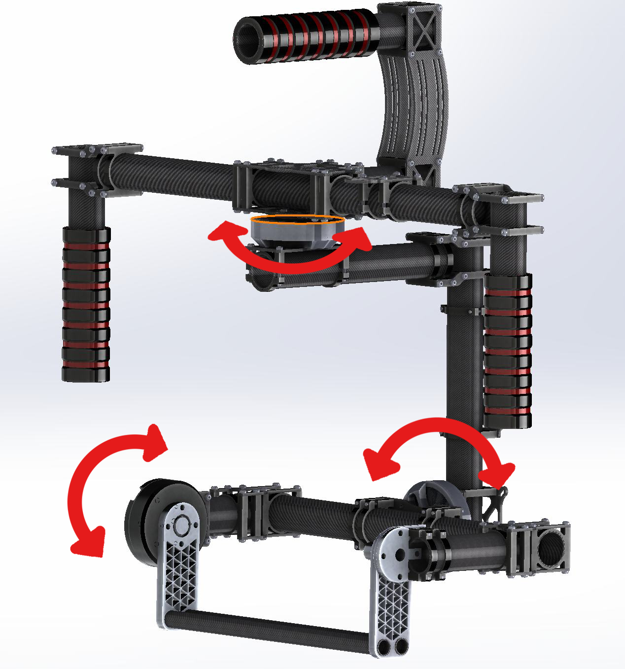
A three-axis gimbal is intended to balance a suspended system, in this case a camera and lens combination. To achieve this, the suspension needs to be able to control the rotation of the suspended system in all three major axis. This is accomplished through control of the pivot of each major axis, with a motor placed on each orthogonal axis. The motors on each axis are then carefully controlled through the manipulation of PID (Proportional Integral Derivative) variables inside a microcontroller. The microcontroller then adjusts power output to each motor through motor controllers and associated mosfets.
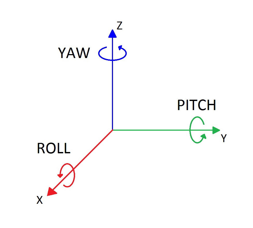
Before we go any further, let's review some terminology. I'm sure you're familiar with a standard X-Y coordinate system and have seen three dimensional (X,Y,Z) Cartesian coordinate system diagrams. A gimbal labels the 3 major axis (X,Y,Z) as (Roll, Pitch and Yaw) respectively. I use these axis names interchangeably going forward.
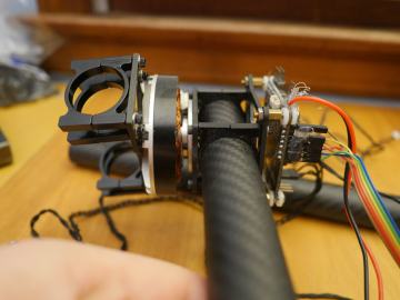
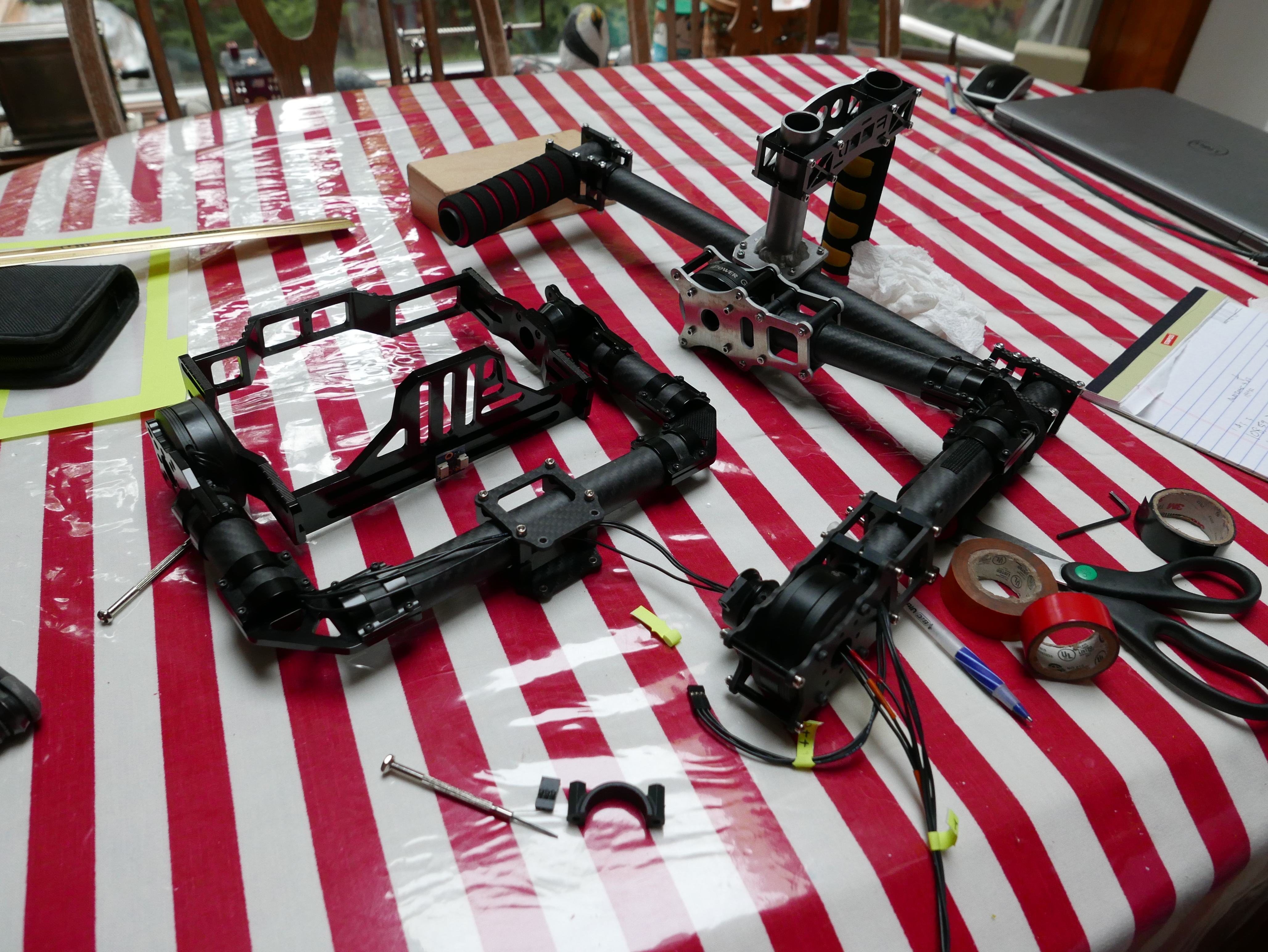
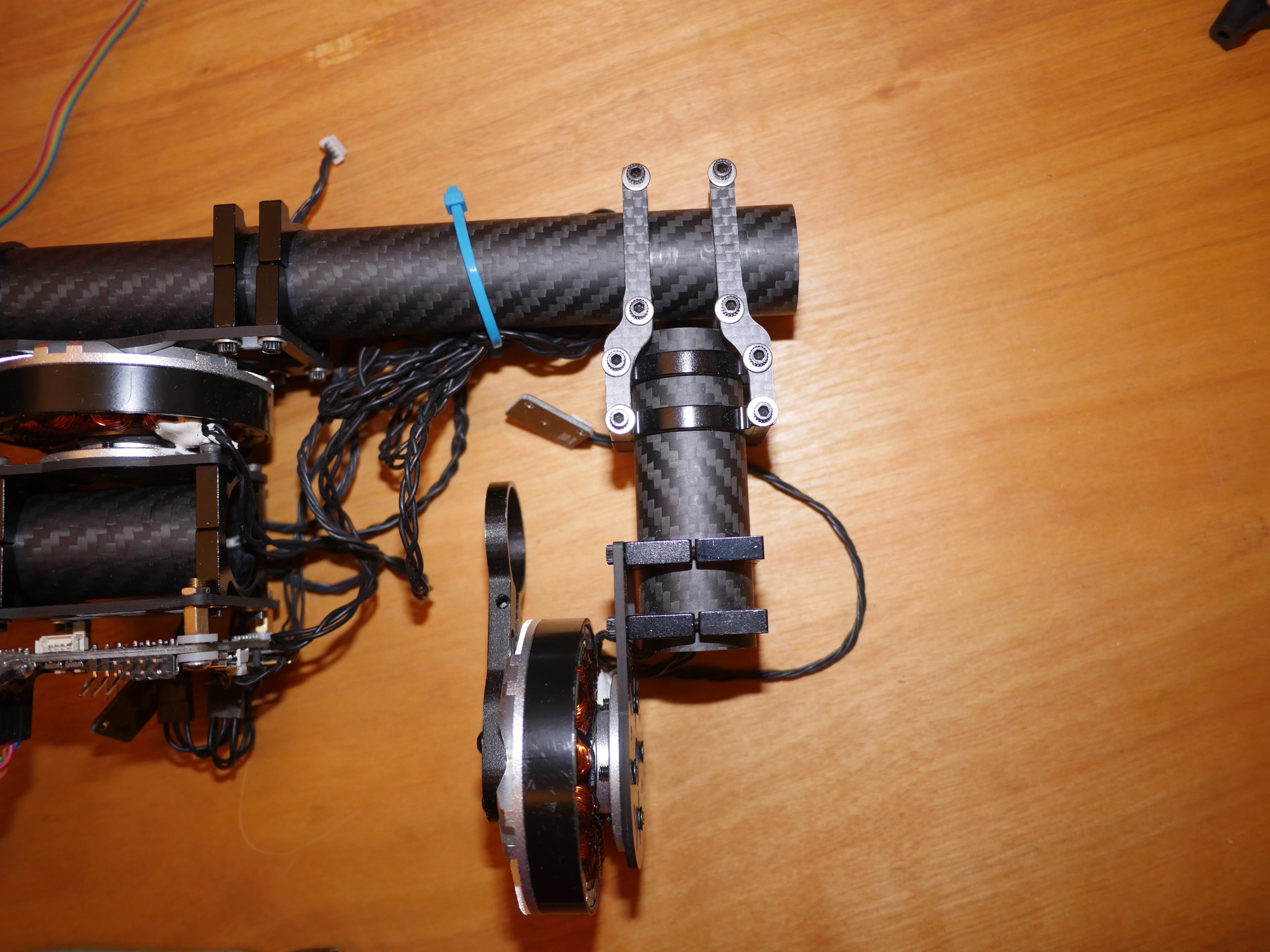
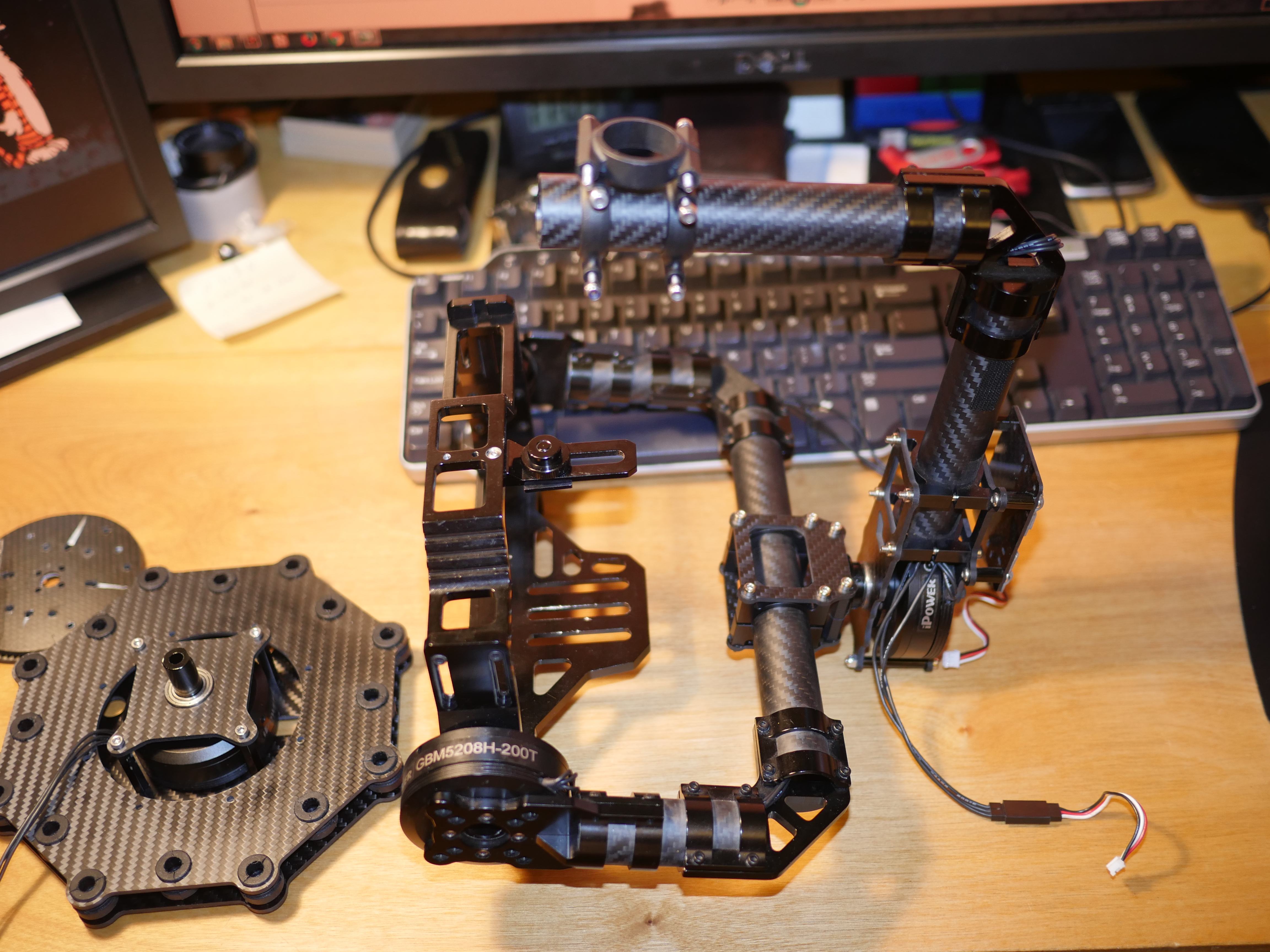
Here is a closer view of the goods. The roll and pitch motor, brackets and carbon fiber tubes were all intact. The yaw motor was unfortunately missing. Luckily the case was full of spare odds and ends, so I set off to create a 2 axis gimbal, and order a replacement yaw motor when I was satisfied with the operation of the X and Y motors.
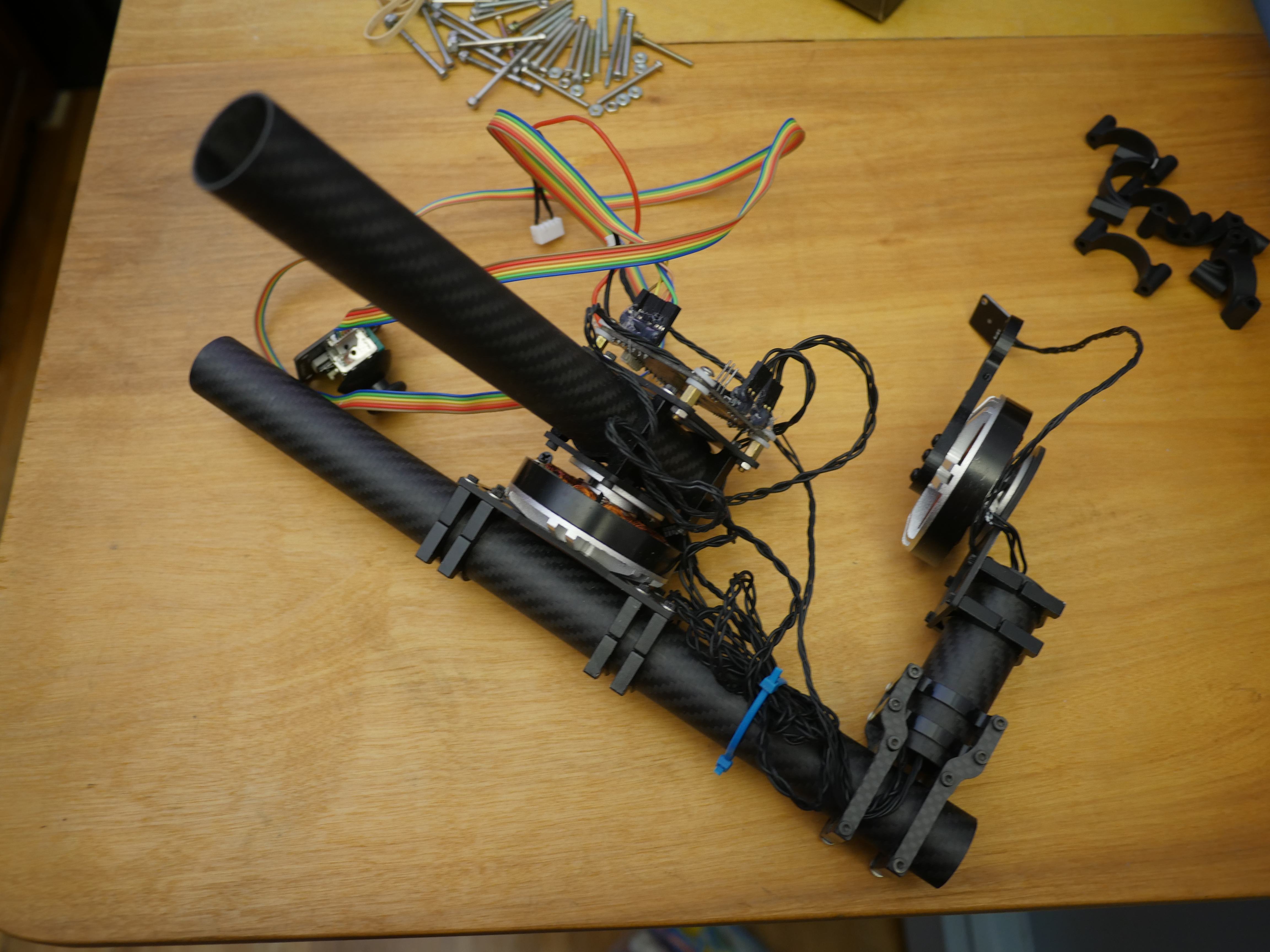
The good news is that the previous owner left a controller! Thus I could actually make the contraption do something while I fixed the mechanicals. Since the gimbal was this far disassembled, I figured I would take a closer look at the carriage assembly and see if I could improve alignment or the mounting hardware. The carriage was rather unimpressive and only offered a simple slot adjustment on the face of the motor.
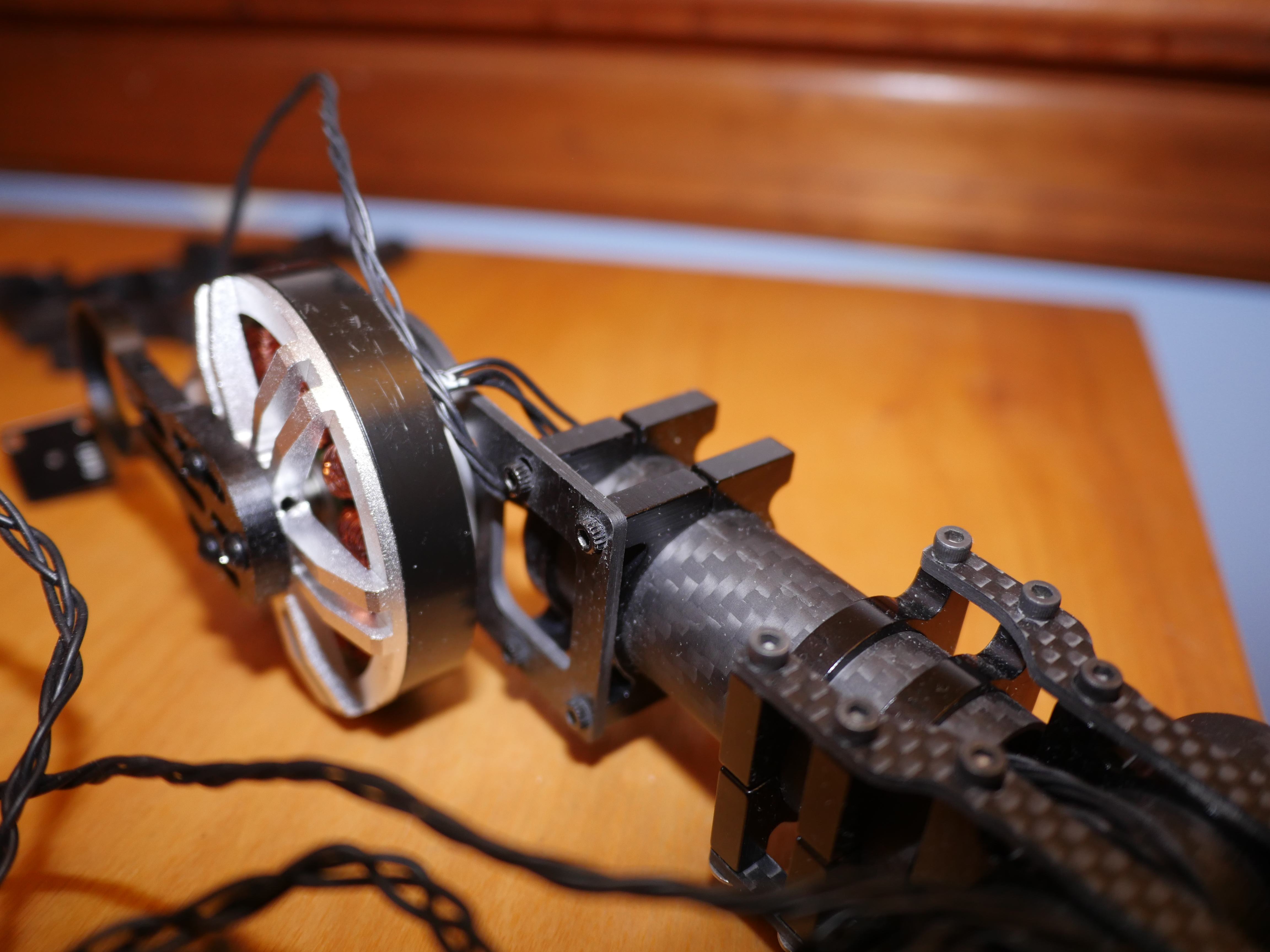
With the carriage removed, I noticed that the roll axis was rather bent. In this image you can see the beginnings of the rotors and windings. That is definitely not a good sign.

I tried orienting the Y-axis motor shaft and the X-axis roll bar balancing shaft so they are parallel. The resulting angle was a bit larger than I was comfortable with. This was not going to be a quick fix, that's for sure.
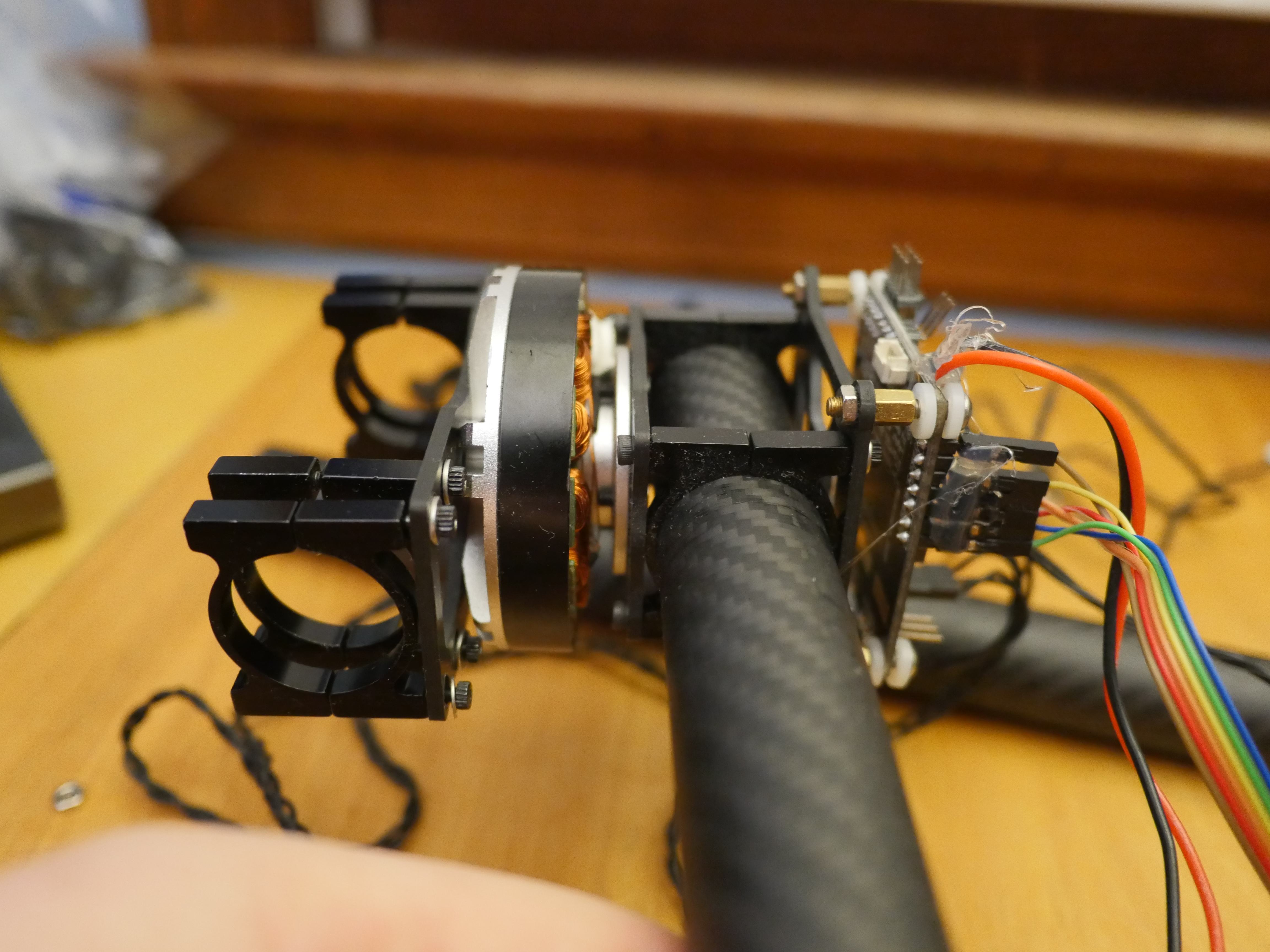
Next up is to focus on the pitch motor. Everything looked to be intact, but the mechanical attachments seemed rather minuscule for my likings.
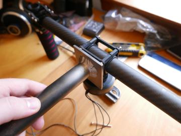
The X-axis motor bracket left a lot to be desired. It was considerably weaker than I would have hoped, and flexed under a slight load placed by my finger. I don't think sway is a good characteristic to have in a gimbal carriage assembly.
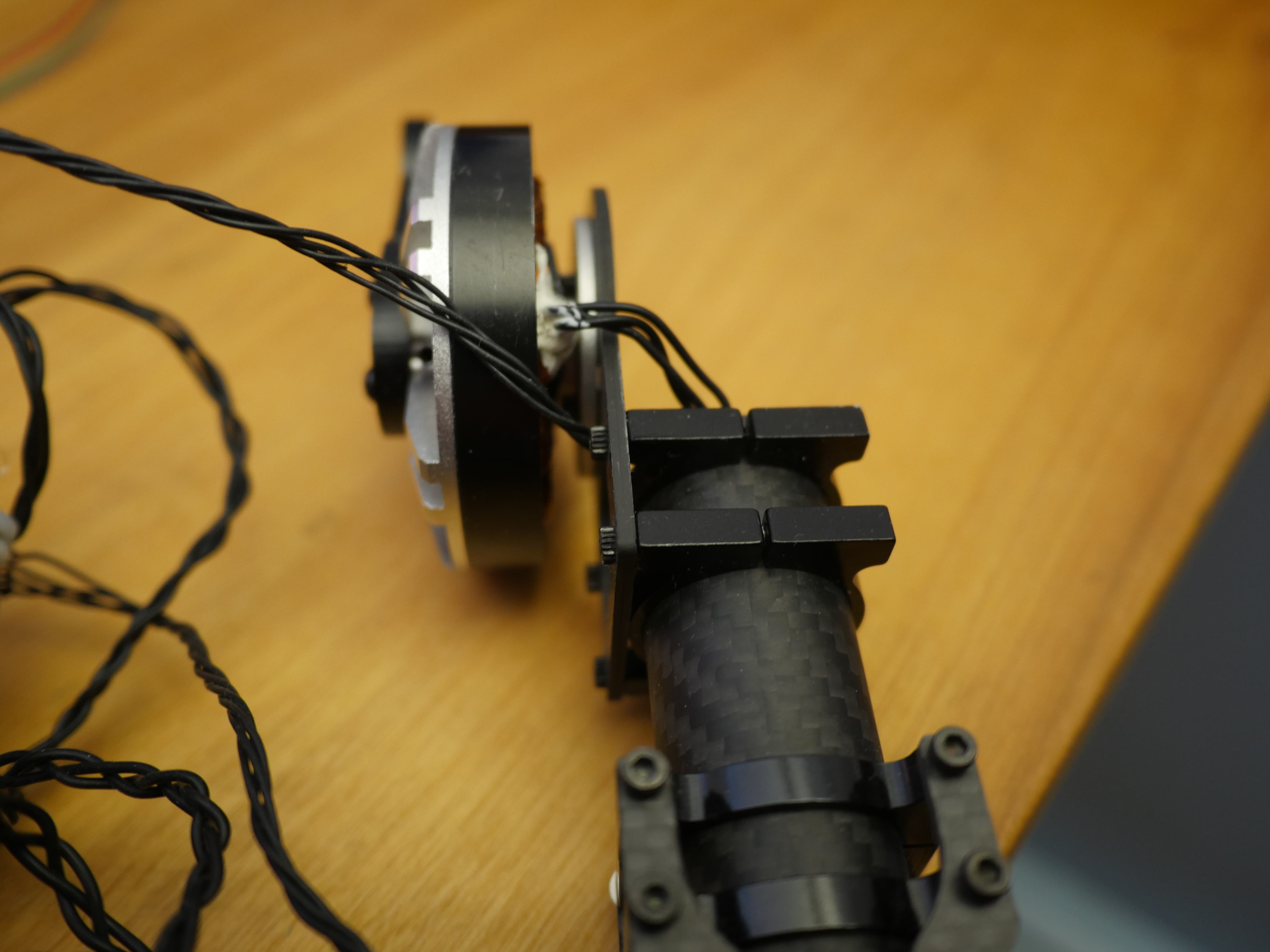
To add insult to injury, the X-axis motor shaft was bent as well. Since both motors were bent, I decided to hold off on purchasing anything for the gimbal, and focused my attention toward making the gimbal function with the parts I had.
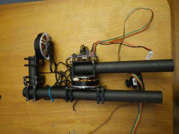
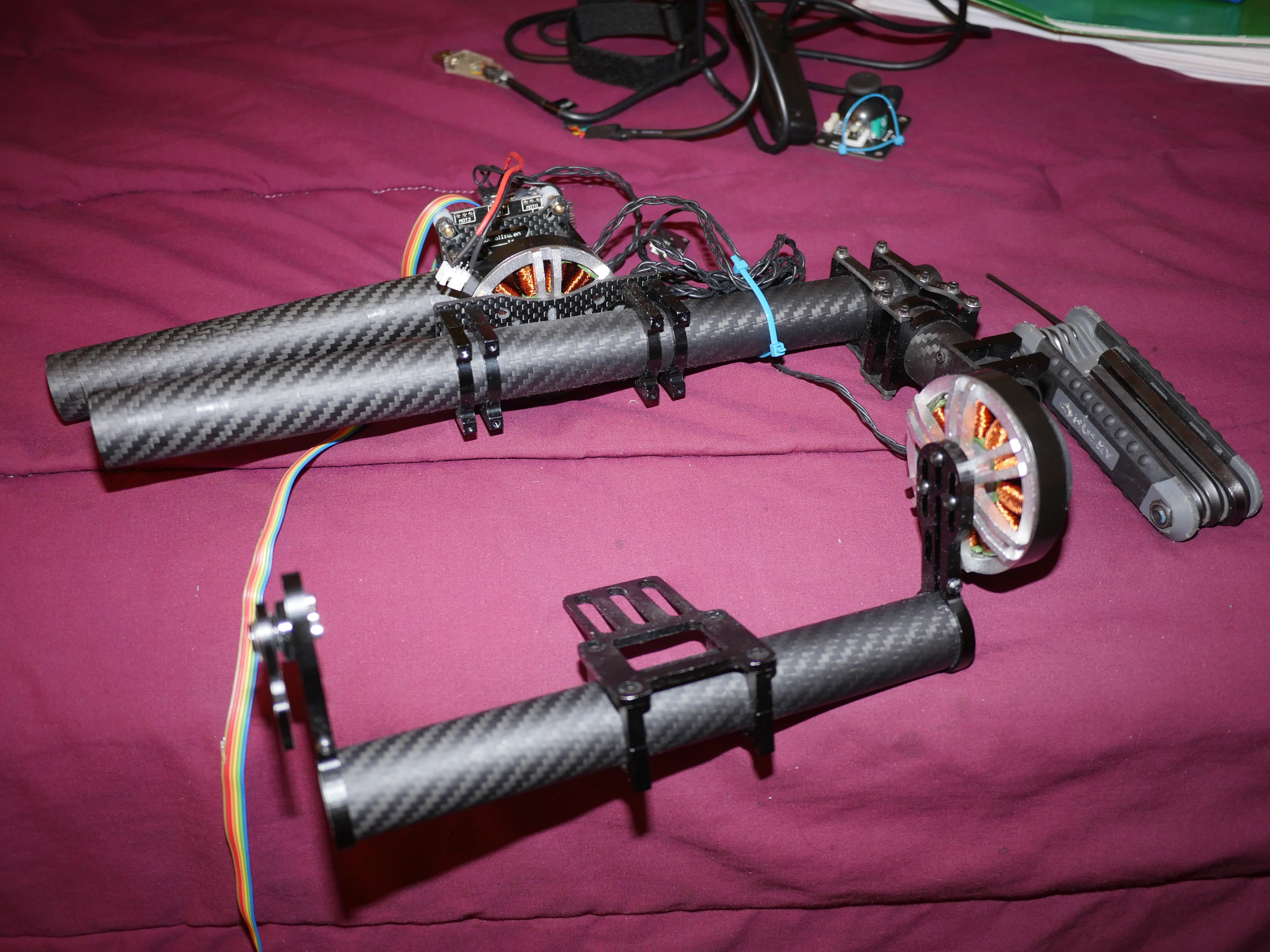
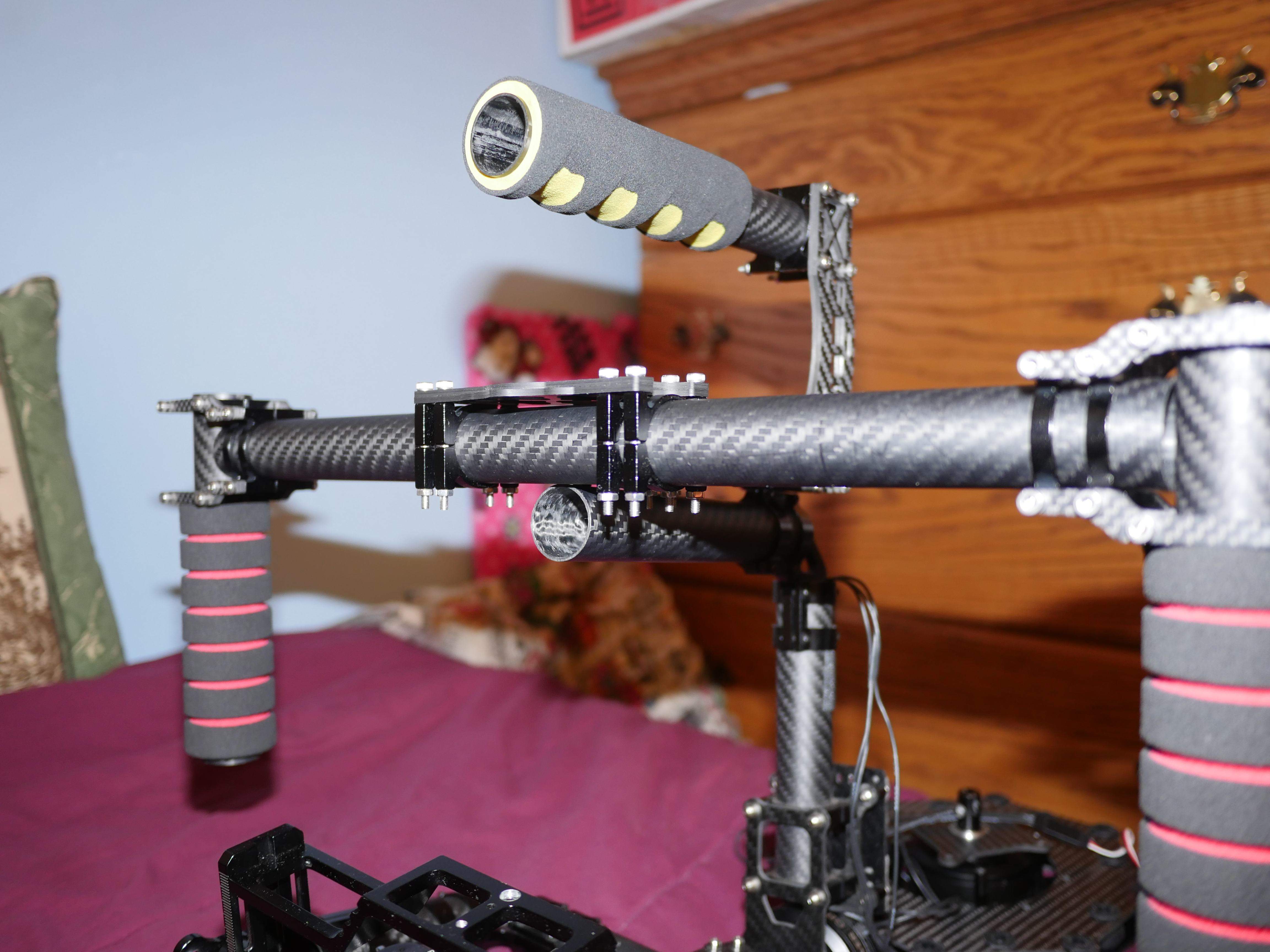
Since I didn't have a Yaw motor, I reconfigured the handle for fixed yaw operation. Luckily, I had enough carbon fiber pieces left over to make this happen.

I noticed that the knurled bolt heads used throughout the gimbal were literally chewing into carbon fiber parts so I added washers to prevent further damage to the brackets.
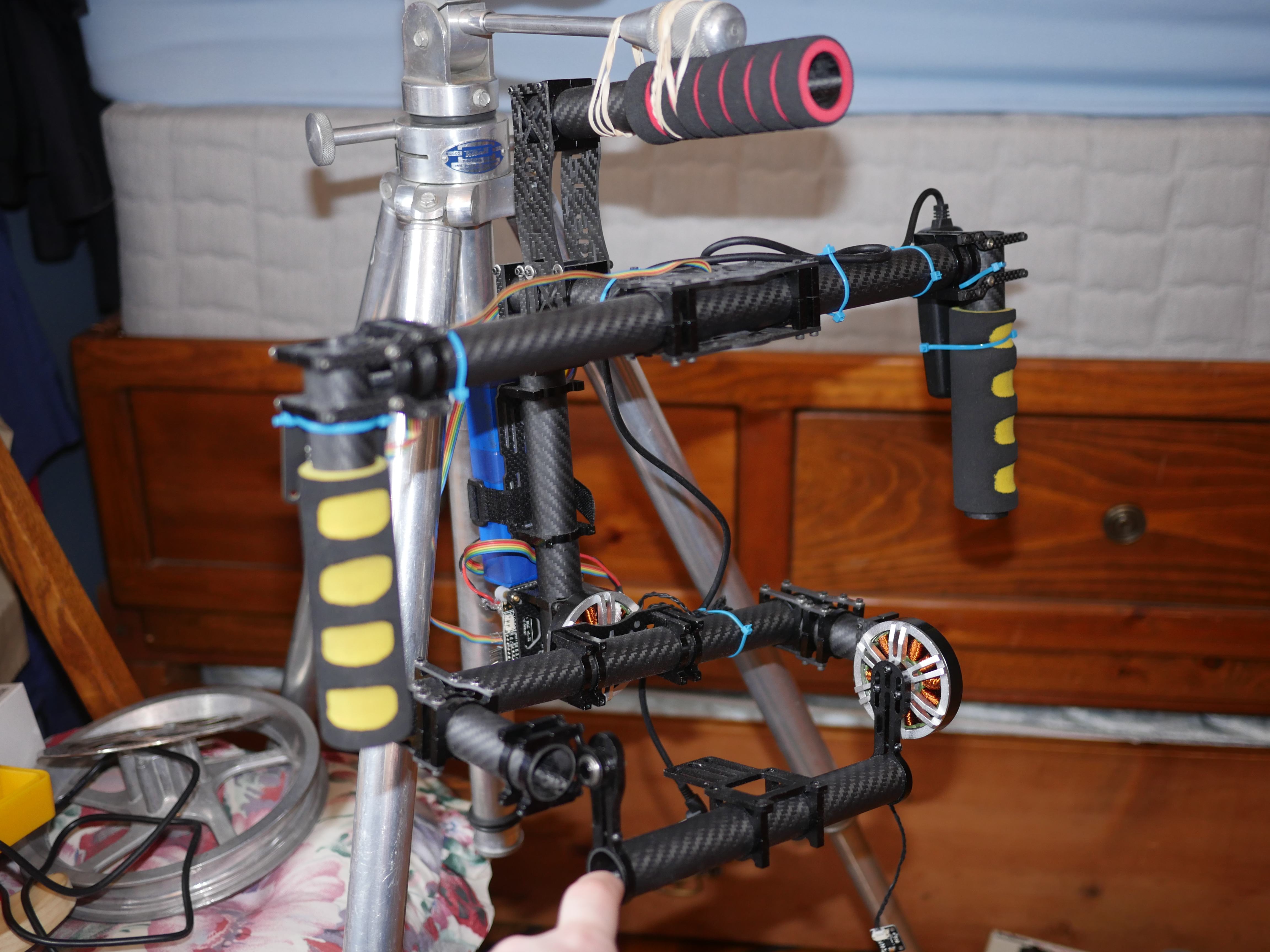
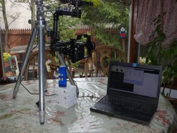
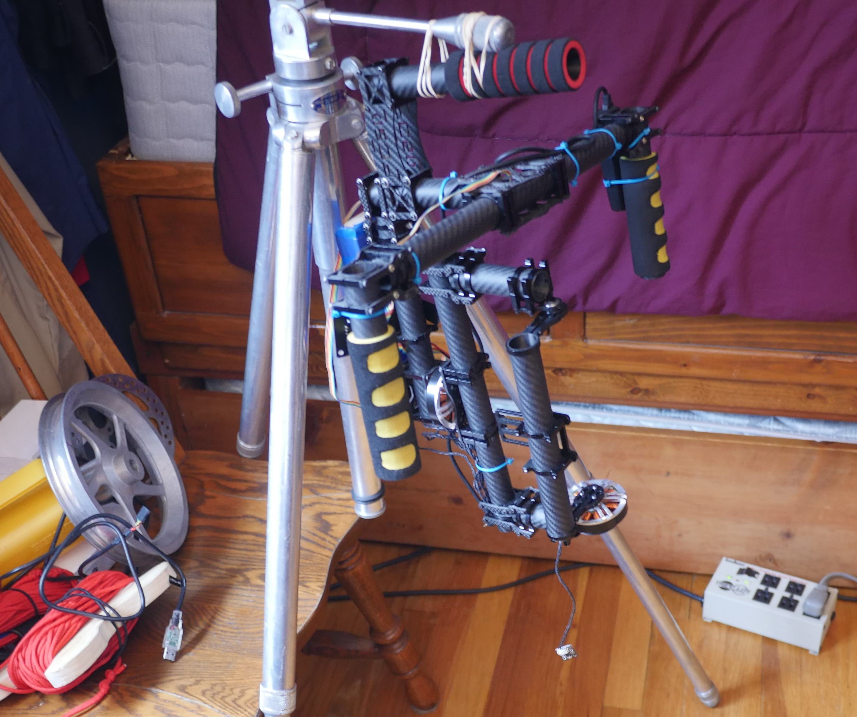
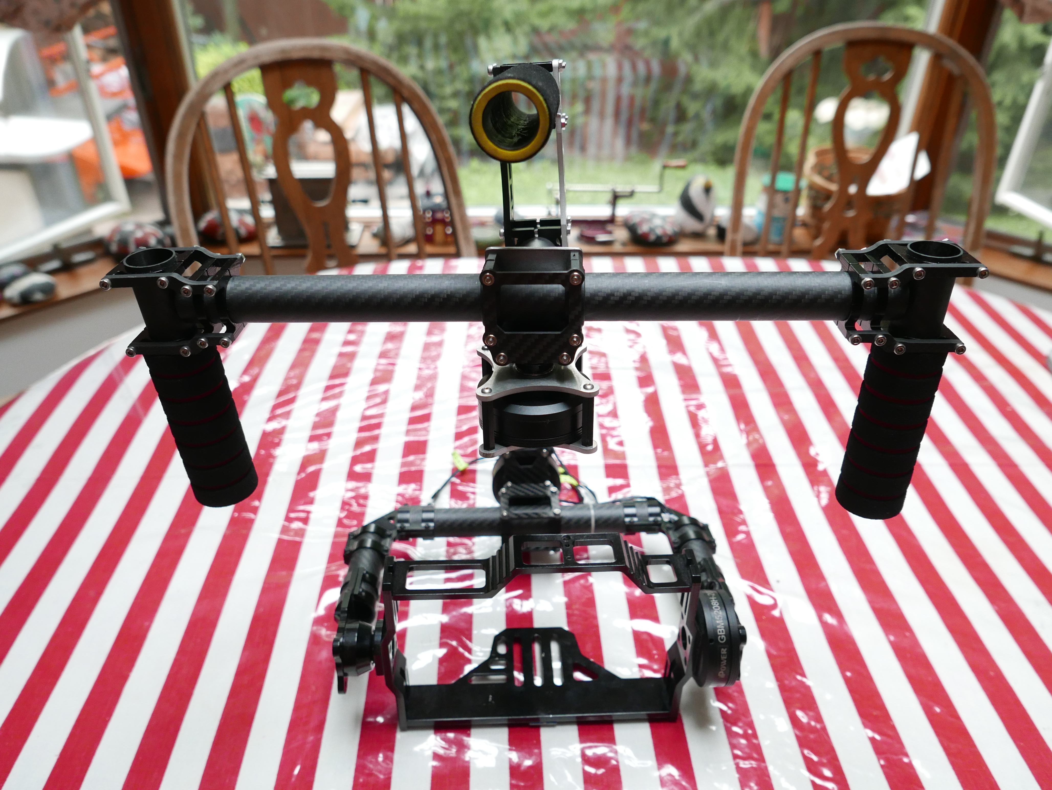
Here's what the gimbal looked like with a rigid yaw axis. I used my old tiltall tripod as a gimbal balancing stand because I simply did not have any other way of holding the gimbal up while I messed with the controller and motor settings. Rubber bands to the rescue!
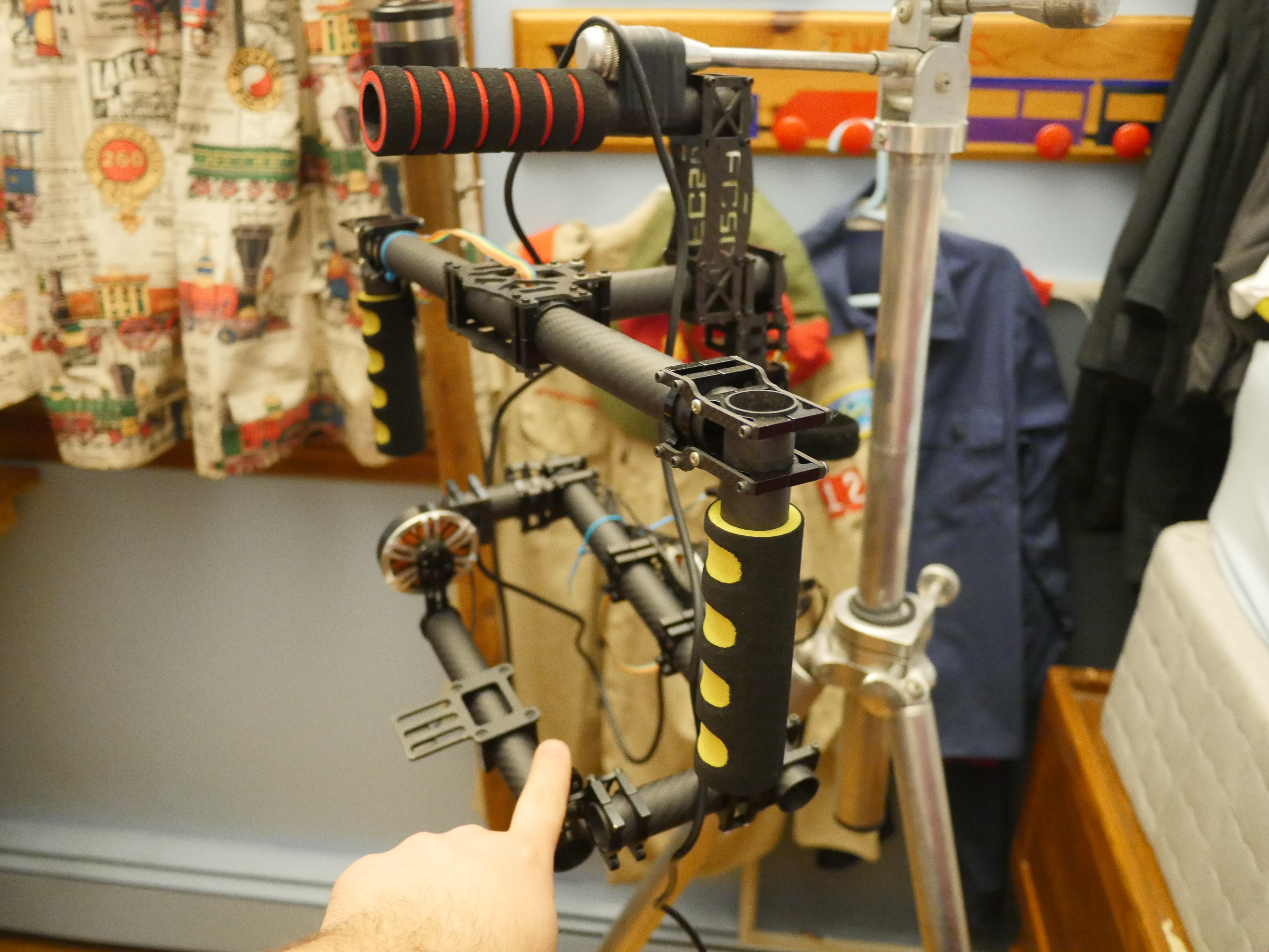
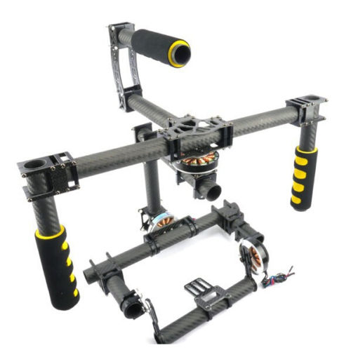
Alternate view. The gimbal really doesn't look half bad assembled. While I was super stoked to find a gimbal like this, there was absolutely no information included in the case. There were also no markings of any kind on the gimbal either. Most of the time, this doesn't matter, but I really wanted to figure out the specifications of the gimbal and the rated stabilization payload capacity.
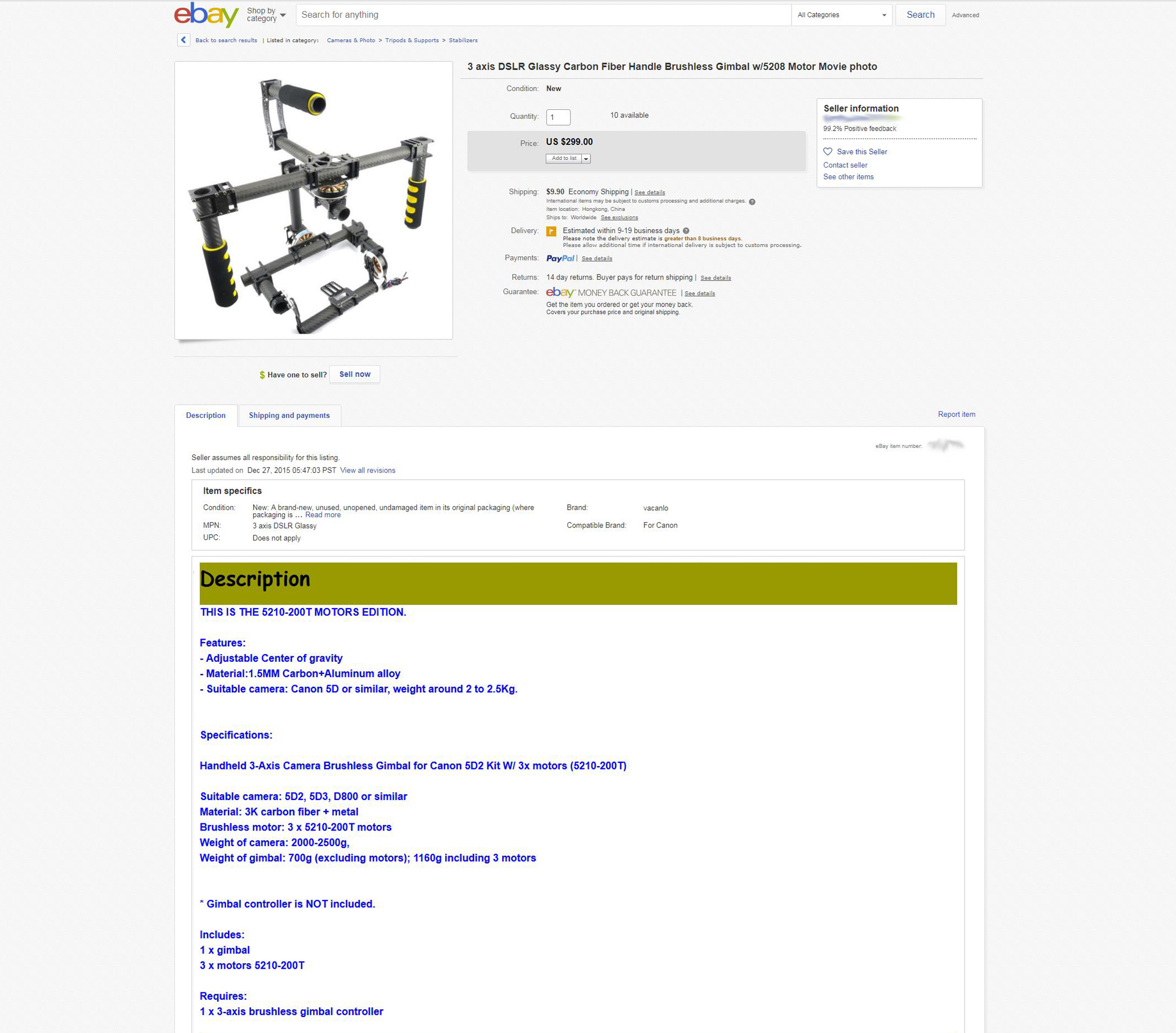
It turned out this gimbal was a 3rd party clone gimbal, commonly found on alibaba or from large Chinese ebay sellers. Such gimbals come in many different configurations but largely share the same parts. My gimbal featured a solid cross bar with a bottom mounted yaw motor. Some gimbals straddle mount the yaw motor and split the top bar in two with the Yaw motor in the middle.
After a bit of research I came to the conclusion that my gimbal was supposed to be configured with (3) 5208 outrunner style brushless motors. 5208 specifies the dimensions of the stator inside the motor. In this case, the stator diameter is 52mm and the stator thickness is 8mm. This means that the outer shell of the motor spins rather than a protruding inner shell that is more commonly associated with traditional motor design. 5208 motors come in a variety of configurations. My 5208 motors feature an open-style solid-shaft design, with 14 poles. The number of turns on the motor windings also vary. Some have 120 turns, some 150, some 200 or 210. Of course, the associated motor inductance also changes based on the number of turns. Since my motors were not labeled at all, I didn't know the number of turns. I took an estimated guess based on the weight of the motor in comparison to similar designed motors sold on alibaba and aliexpress. I also based the motor inductance around these 3rd party motors, since it turned out that the values were fairly consistent between 5208 motors of similar number of turns. Some of this information may seem trivial, but it will become a lot more important when it comes time to program the controller.
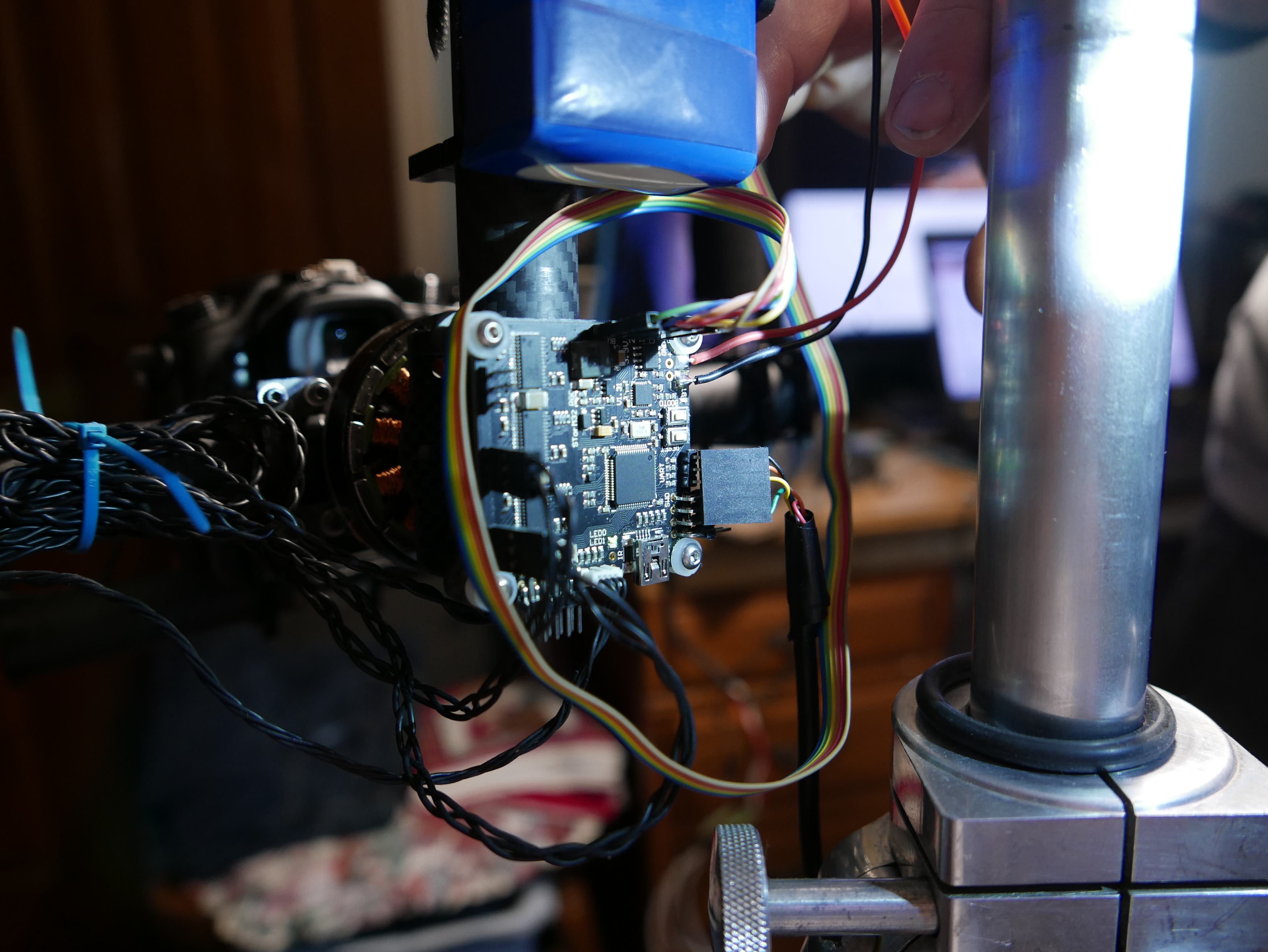
A bit about the controller. This gimbal relies on an open source controller, the STorM32 BGC v1.3, which drives the roll, pitch and yaw motors. Specifically, this uses a 32bit ARM Cortex M3 microcontroller and (3) high-speed mosfets for driving the 5208 brushless motors. Like many other microcontrollers, this one uses a USB-to-serial interface for programming the EEPROM and updating firmware.
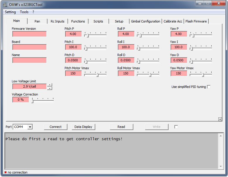
To communicate with the microcontroller, olliw has designed an open source program dubbed "o323BGCTool." This program offers a lot of functionality, such as the adjustment of PID (Proportional Integral Derivative) values, calibration of motors and IMU (Inertial Measurement Unit), display of the live output motor data, and the ability to set motor offsets. you can also calibrate the motors, flash firmware, configure an optional Bluetooth module, and of course, level the gimbal.
After messing with the o323BGCTool for a few hours and troubleshooting the hardware for an additional few hours, I was finally able to make the gimbal move. I realized that you could disable the z-axis motor, making the calibration of the X and Y axis motors significantly easier, as the calibration would never complete setup without a Z-axis present. With some fiddling, the X and Y axis motors would rotate about. The rotation was by no means perfect though. Each motor looked like it was trying to overcome a terrible spasm. It took me a while to determine the root cause of the motor spaz attacks. I originally started tampering with PID controls and power allocation to the motors. There were slight changes, but nothing significant. It turned out that the pole count on the motors was set wrong. The motors were 14 poles, not 16 which was was the pole count default. After another round of balancing and motor recalibration, I was able to make the gimbal move more calmly. With a bit more testing, I was finally able to get the x and y axis motors to stabilize. Unfortunately, even after hours of testing and experimenting, the gimbal never quite remained consistently steady. I put a test camera and lens on it, in this case a small lumix GF1 +20mm, and the gimbal just simply could not stabilize the camera continuously. It would feel like it would have the power to stabilize, but all of a sudden it would give up and lose position and have to reset itself. I tried again to adjust power and PID values. I also changed power sources from a 12v battery to a 16v battery, hoping that the additional potential difference would provide a bit more leeway in the tuning of the motors. This was not enough. I came to the conclusion that the mechanical damage sustained by the motors had caused the failures associated with stabilization. The added friction between the rotor and stator caused by the bent rotor shaft just simply overloaded the small motors.

I was a bit bummed out that I could not get the gimbal to remain stabilized. So I focused my energy on analyzing all the mechanical failures of the gimbal and resolving them. For one, the method used to attach the gimbal motors to the carbon fiber components was completely horrific. Instead of using a mechanical component to bare the load of the carriage and having the motor rotate that mechanical component, the designer of this gimbal simply used the motor as the load bearing component and the agent to rotate it. No wonder why the motor shafts were bent. The motor axles took the entire load of the system! The Y-axis motor looked to suffer the worst. Instead of just the wait of the carriage, the Y-axis motor carried the weight of the X-axis motor, the carriage, and the balancing bar. Of course, no mechanical sleeve or bearing was used to support the load placed on the y-axis either. That certainly explains the double digit off-angle measurement between the Y-axis shaft and the balancing bar. I guess there's some reasoning behind why the Z-axis motor was missing from the gimbal. I can imagine that it was completely toast.
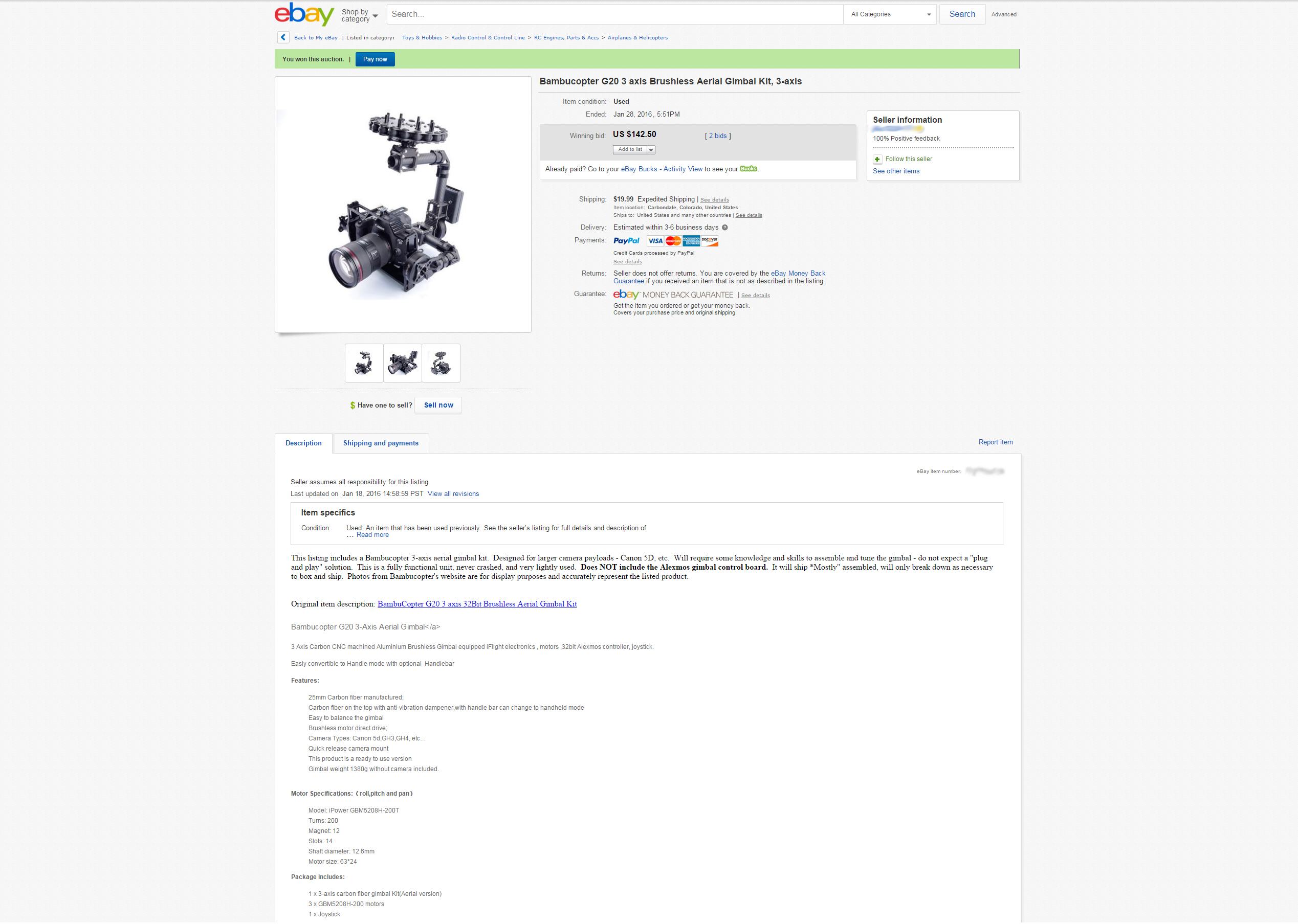
In need of replacement motors, I put aside the project for a bit until I ran across a "for-parts" gimbal on ebay. This gimbal looked like a perfect repair platform for my gimbal. The listing included (3) 5208 motors, a sturdier carriage, the mechanical components for the Z-axis motor mount and various extra carbon fiber bits.
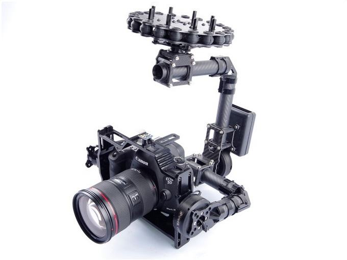
The new gimbal is quite the departure from the old one. For one, this gimbal was designed to be mounted to a quadcopter or octocopter and does not feature a handle bar. Otherwise, the new gimbal implements a closed camera cage, instead of the half cage of the old gimbal. The cage is also all aluminum, which adds quite a bit of mass to the gimbal. I may end up changing this out if I run across spare 12mm carbon fiber tubes and brackets to make a lighter square camera cage.
The motors on the new gimbal are not exactly the same as the previous ones. The new gimbal makes use of hollow shaft brushless motors. These hollow shaft motors actually share the same dimensions as the old motors, which makes the retrofitting process extremely easy.
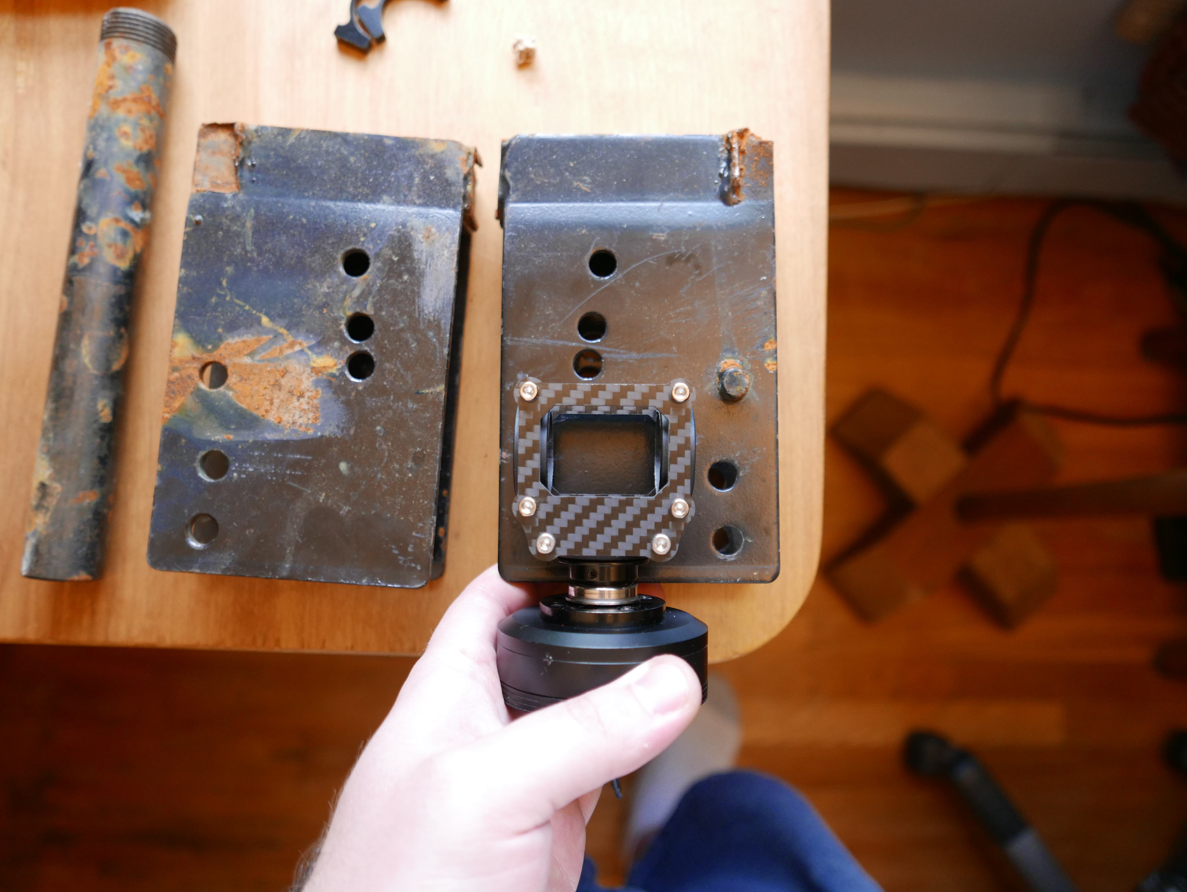
Why the fuss over the new motors? The hollow shaft motors address all the mechanical problems associated with the motors on the old gimbal. The hole in the center of the motor allows for an extruded axle to protrude through the motor and bear the load of all unsprung masses.
Take the X-axis motor which controls the roll of the camera cage. Previously the X-axis motor was loaded with the weight of the camera and the carriage. Now the carriage assembly is directly attached to an axle that bears the associated mass of the carriage and camera. The X-axis motor is free to just control the rotation of the carriage assembly and not the gravitational forces placed on the camera and carriage.
Note: I built off of the 3 axis gimbal CAD of HG on GrabCad. He posted up a CAD model of a gimbal nearly identical to my original gimbal and saved me a bunch of time. Hats off buddy :D
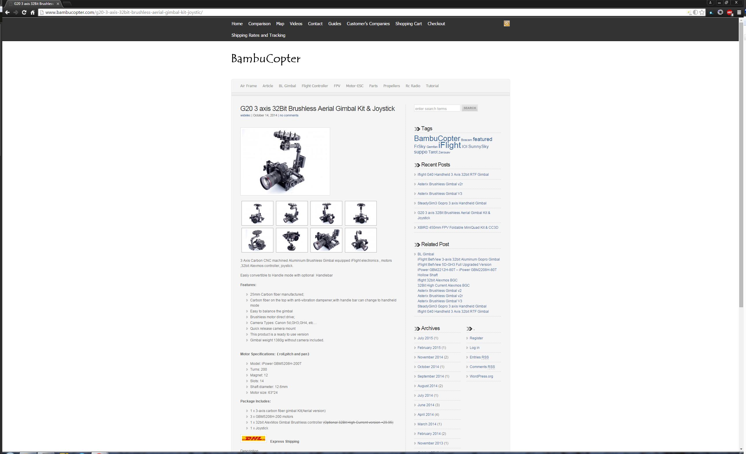
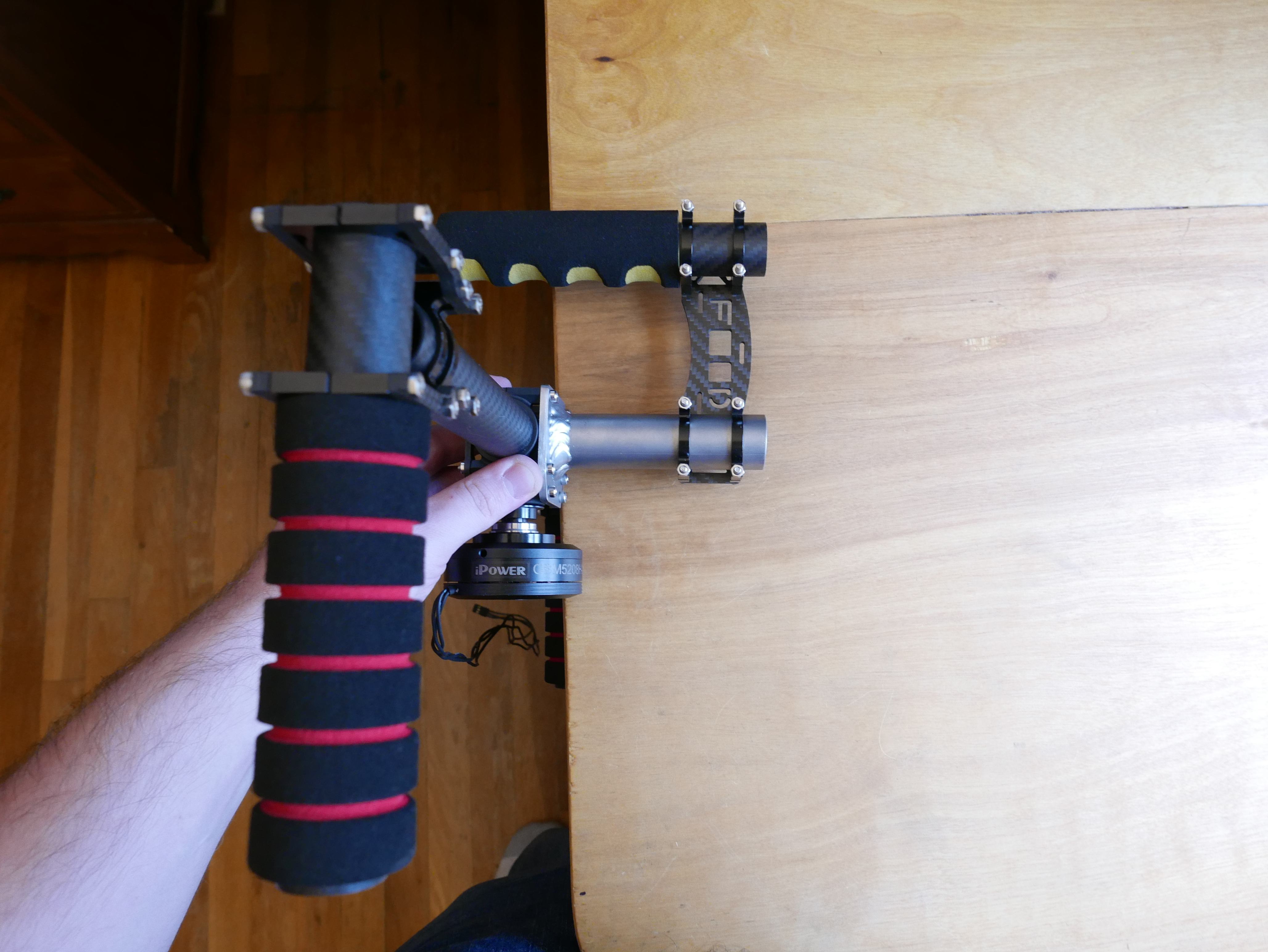
Just like the previous gimbal, this one had no information associated with it. After some reverse searching and scouring the usual 3rd party sellers, I found some hard details on the gimbal. It's a BambuCopter. Whatever that means. The good news is that I have the detailed motor specifications! iPower GBM5208H-200T. 12 magnets, 14 poles, 200 turns and one happy camper :D
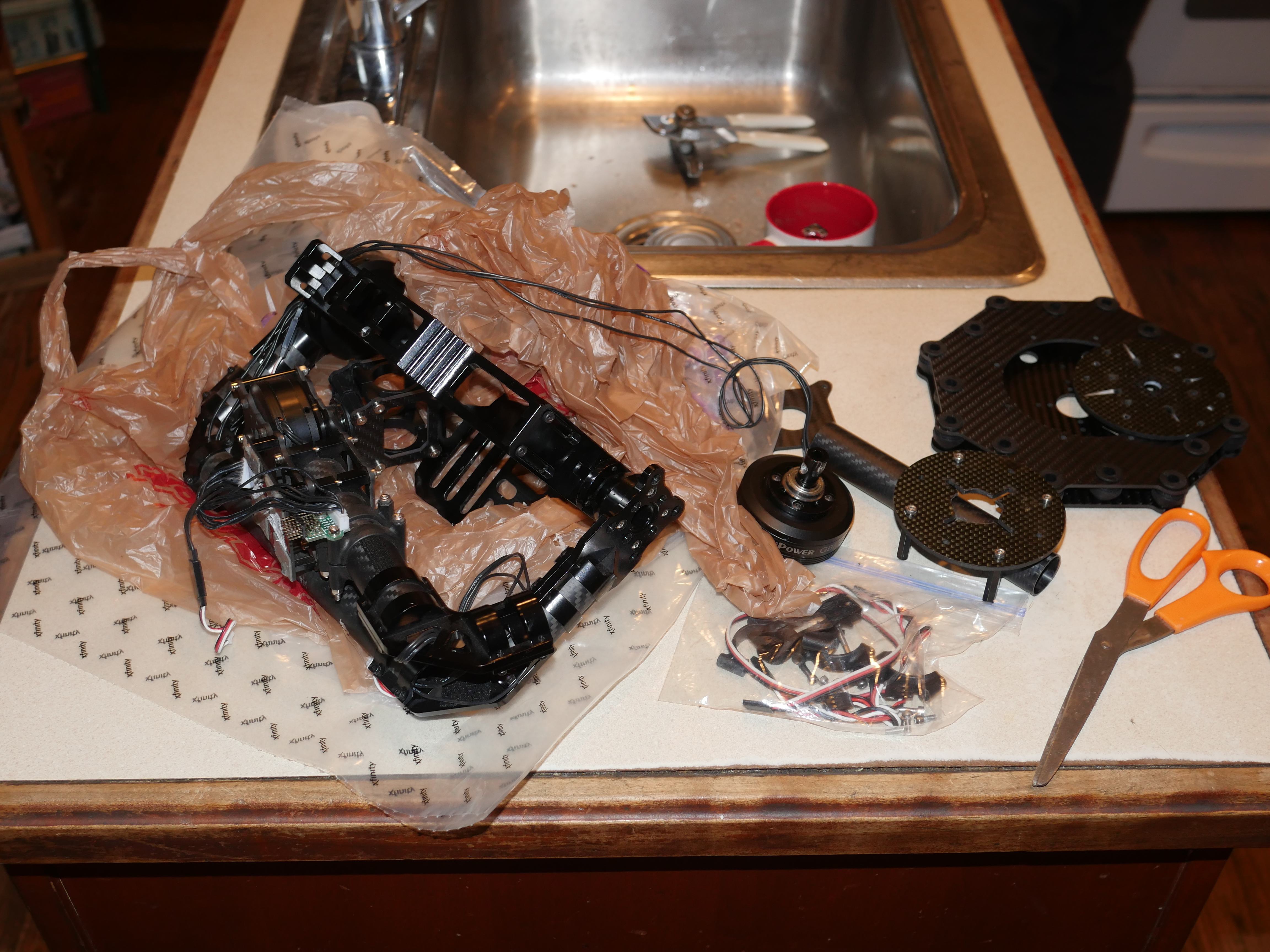
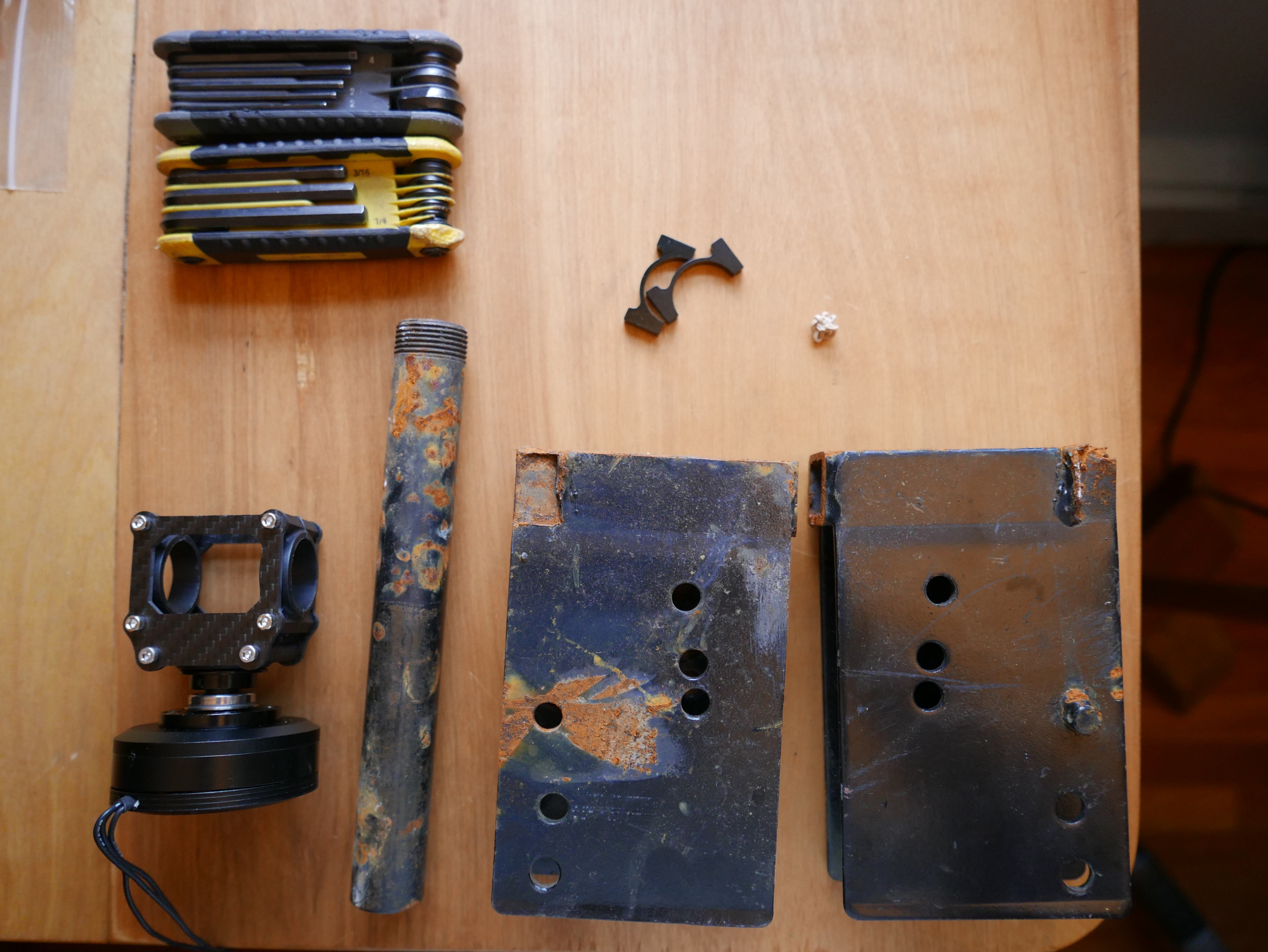
Pile of parts.
The new gimbal in a more finalized state. The flight gear and dampener was not needed, so off they went.
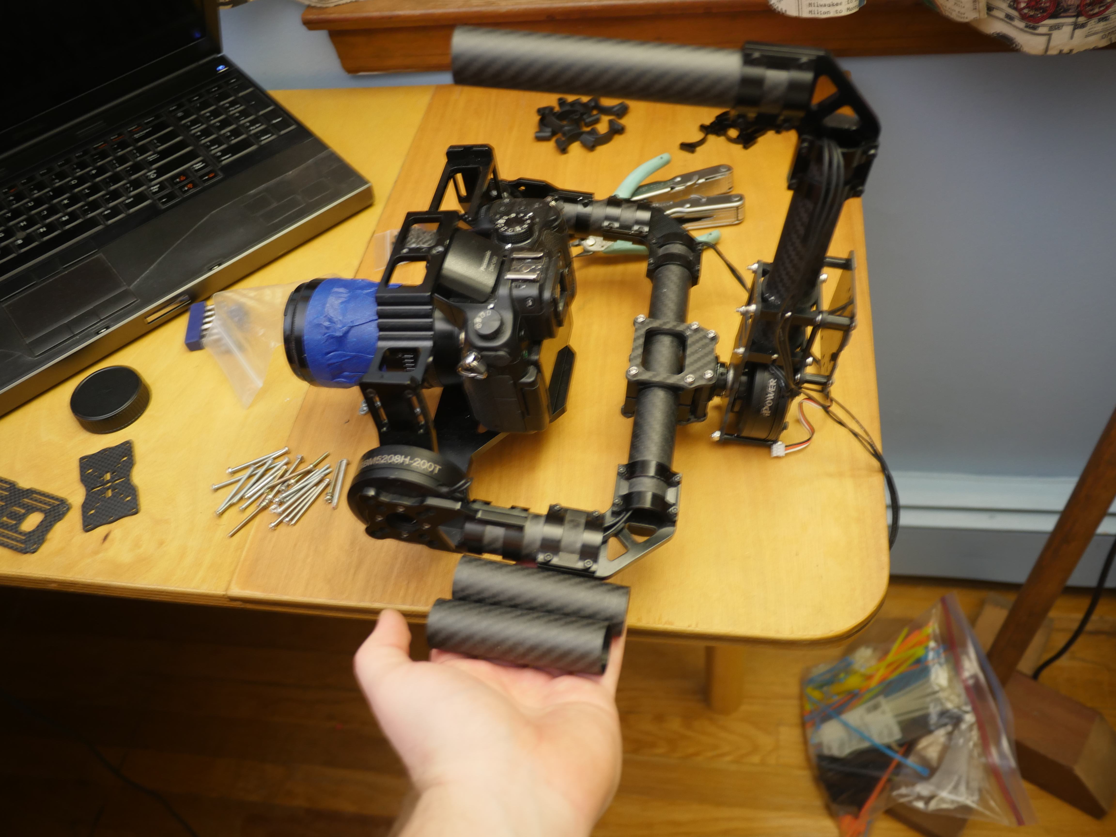
Test fit time! The camera cage was quite accommodating and fit my GH3 camera easily. I experimented with the X-axis motor carbon fiber tube length to better concentrate the center of mass toward the center line of the gimbal, measured from where the Z-axis motor would mount.
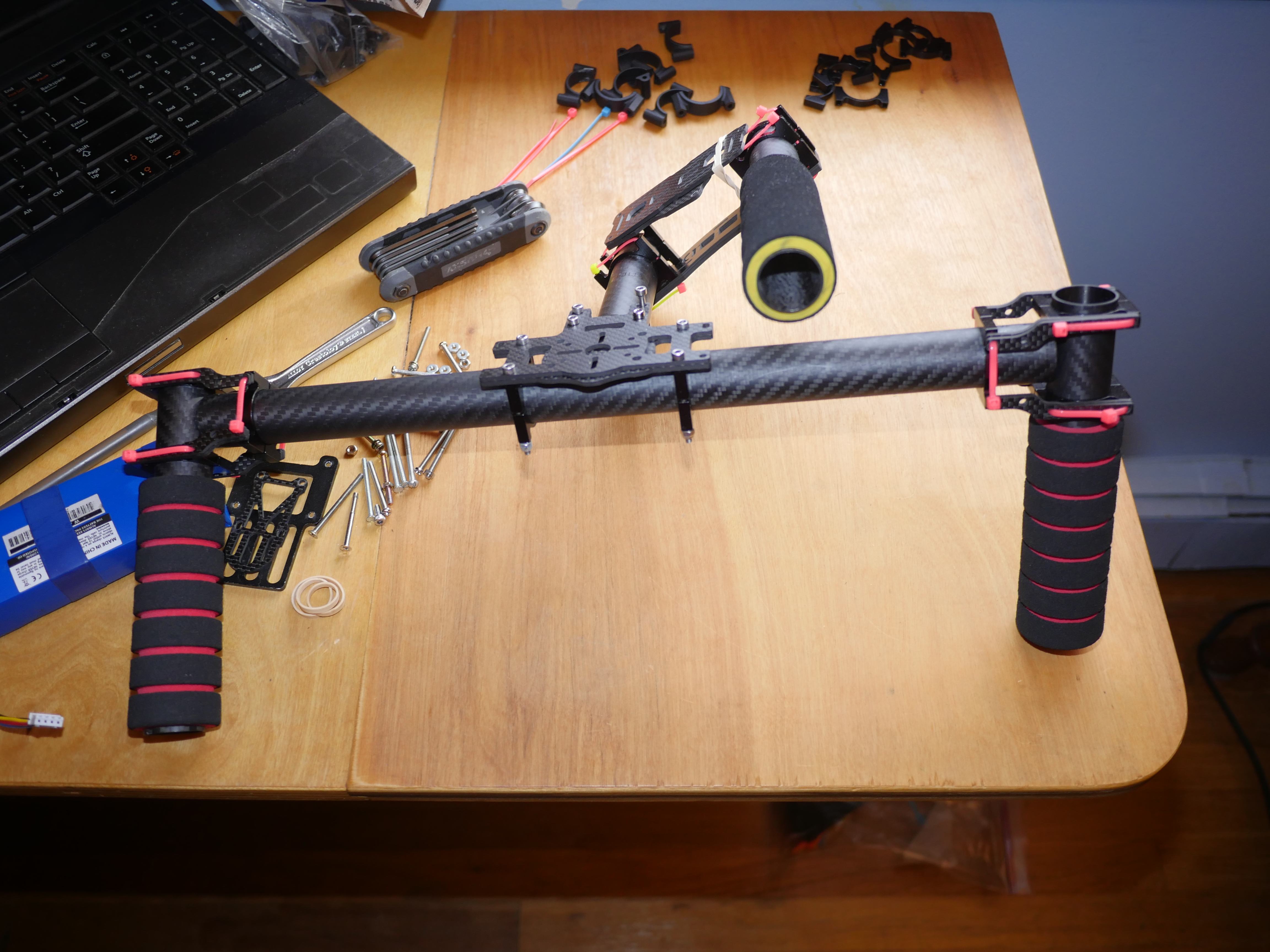
With a new Z-axis motor, the top handle bar was in need of some serious modification.
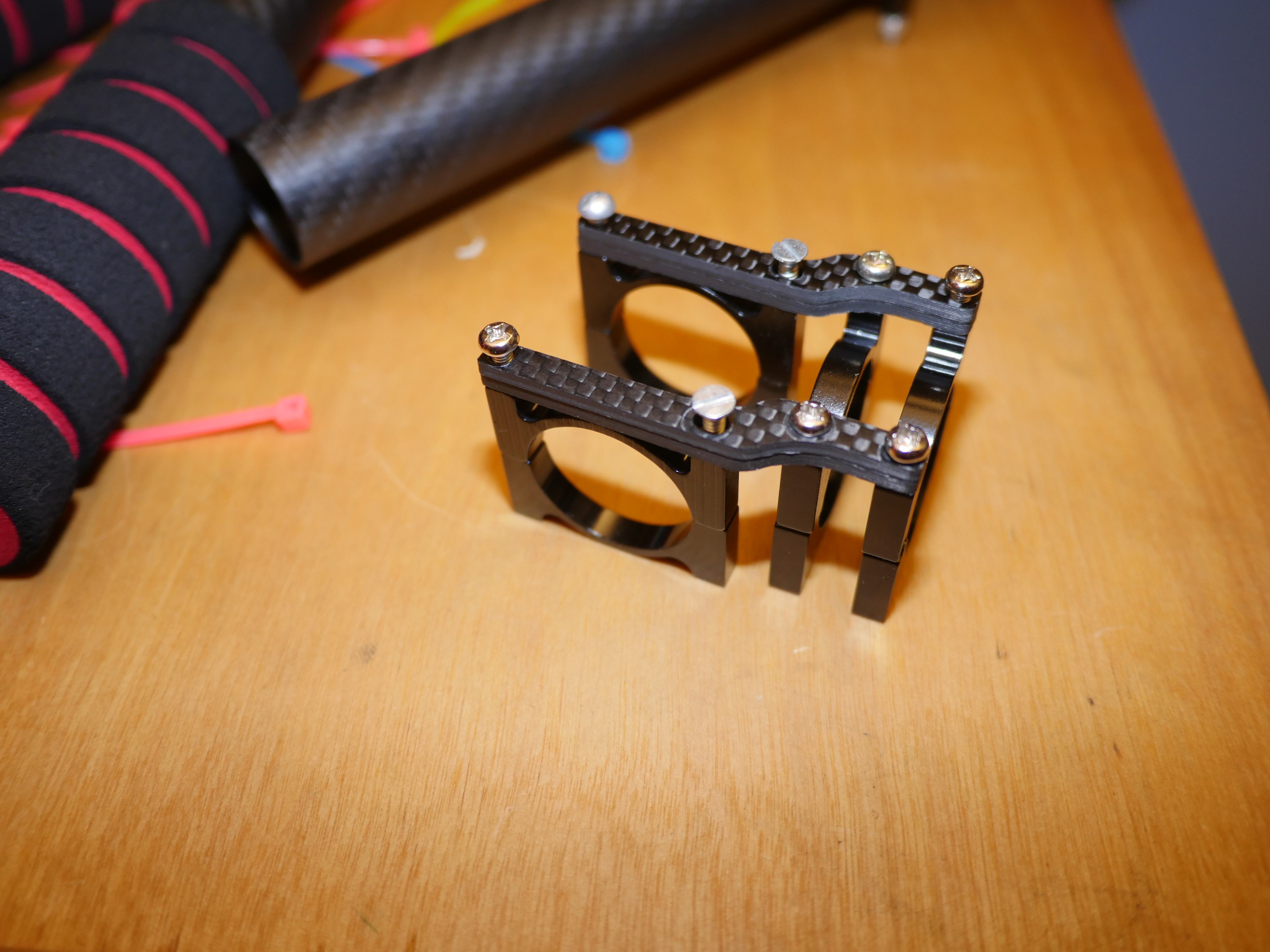
I decided to beef up the construction a bit and double up the carbon fiber strips. The individual CF pieces were ~2mm thick.

Of course, the original mounting hardware was not long enough to accommodate the additional width, so off to the hardware store.
So close, yet so very far. The handle bar subsection was nearing completion, but I was missing several key mounting brackets. I needed a bracket to hold the motor to the y-axis motor shaft, a bracket to attach the top handle to the bike bars, and an additional top handle support bracket.
I was a few mounting brackets short of completing the handlebar, but those brackets were rather custom. I really didn't want to spend the time searching for the right size bracket on ebay or alibaba and then wait a month for them to arrive, so I went ahead and just made them.
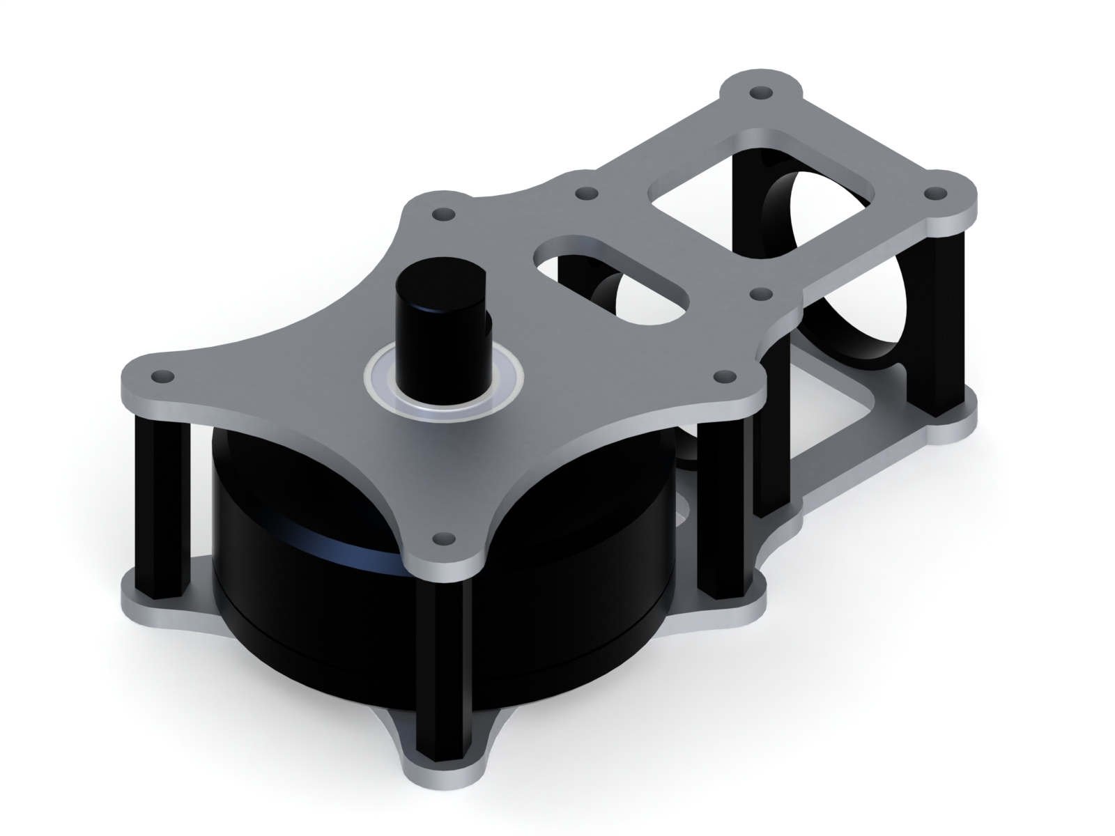
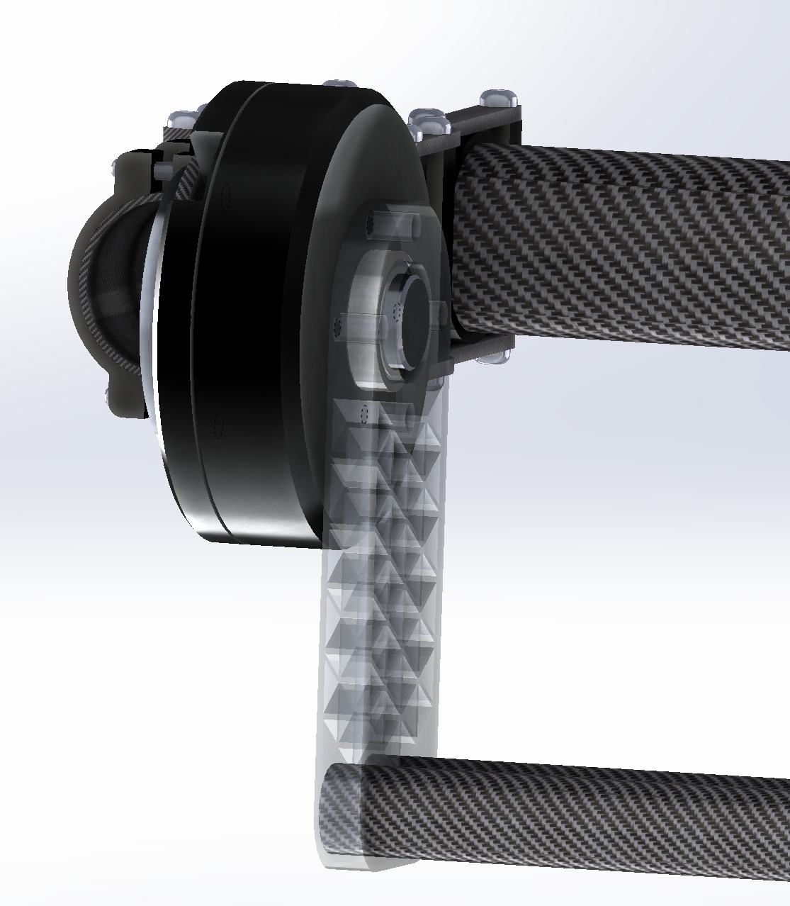
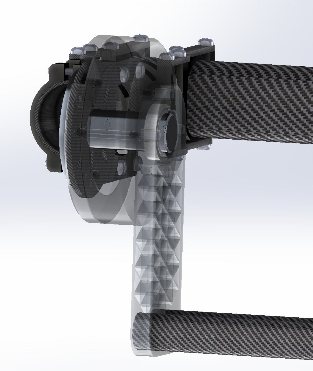
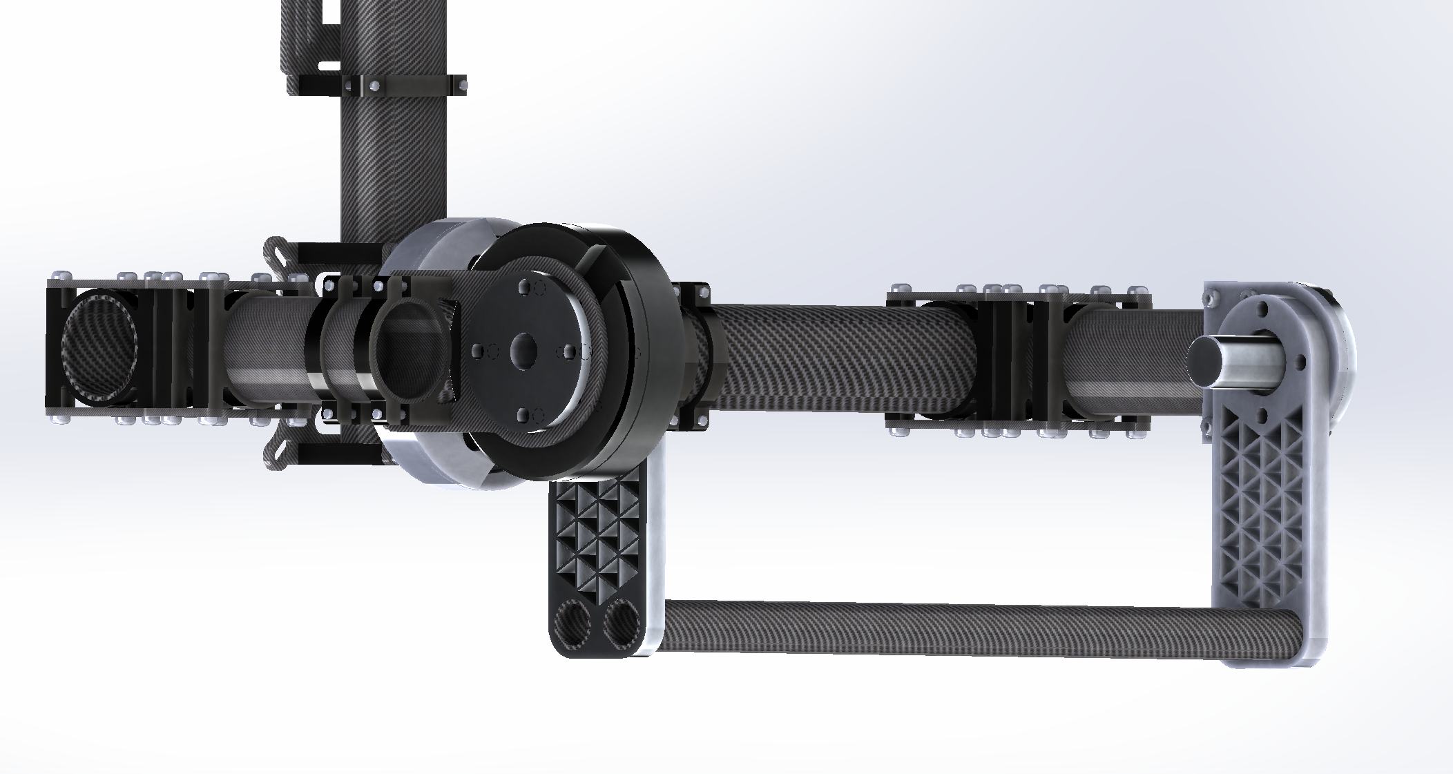
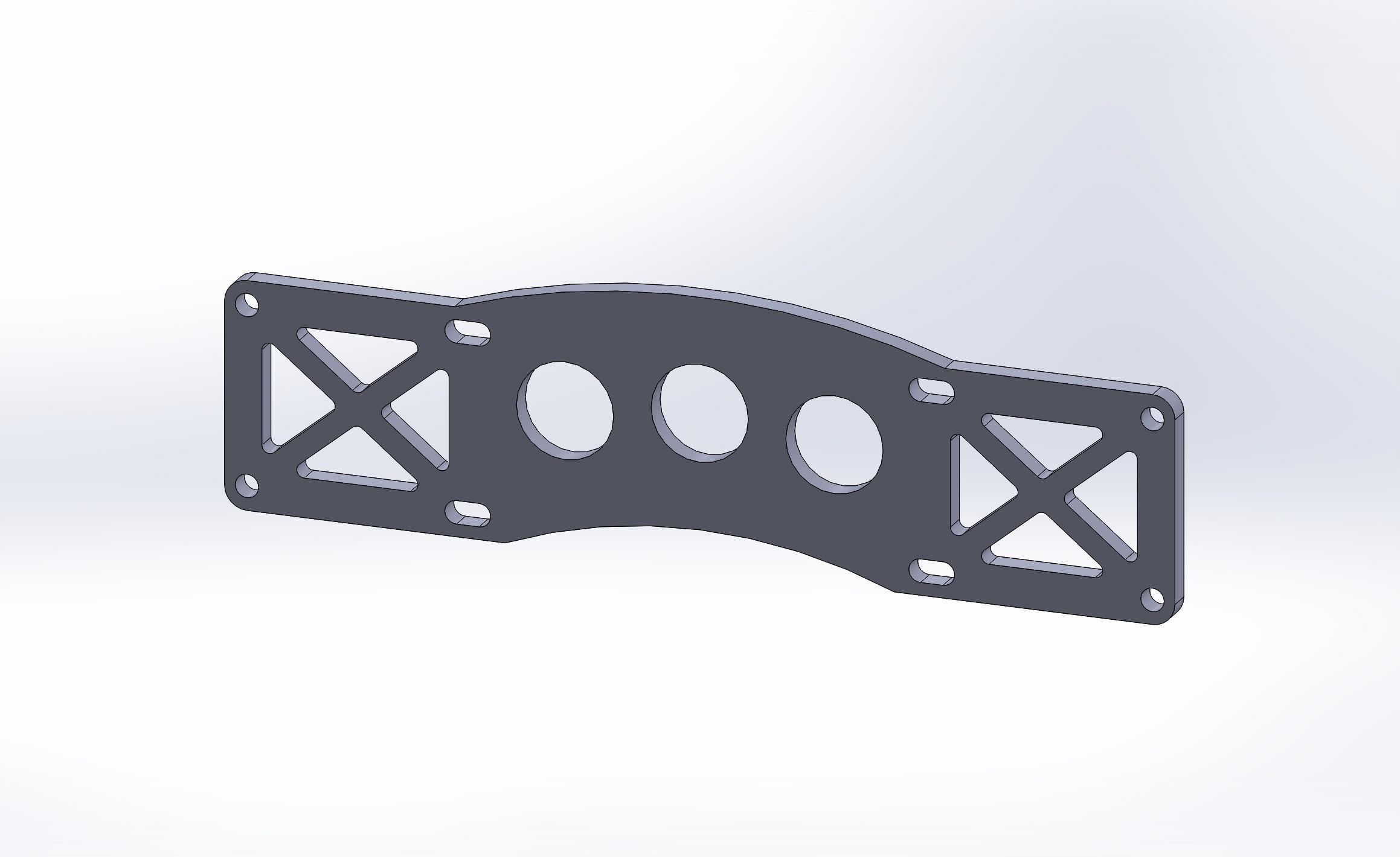
I designed the motor mount to mimic the design of other well established gimbals. A simple motor cage made out of aluminum and extruded hexagonal standoffs looked to be the perfect fit for the gimbal. This is a render of how the final assembly would look. The hollow shaft motor features a simple flanged extrusion that mounts to the motor, and a flanged bearing sits on the shoulder of the flanged extrusion.
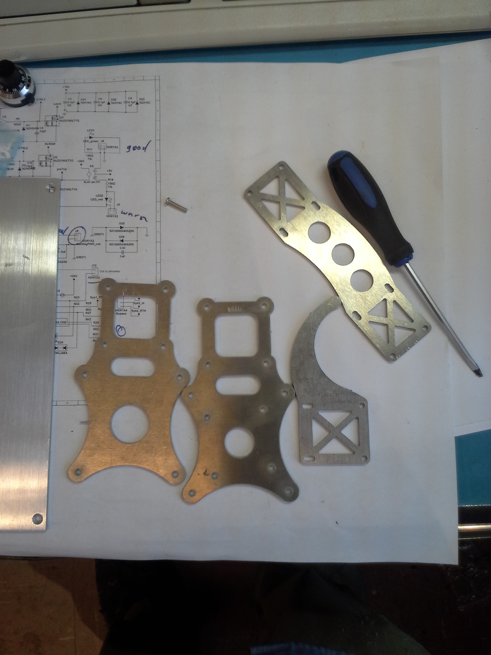
Since I would have to waterjet the motor mount brackets , I figured I would waterjet a bunch of other components too. I designed a handlebar bracket and some hooks for a future gimbal stand.
I was pretty satisfied with how the motor cage came out. It really started looking like a gimbal again!
There was still another component in need of creation: the top handle tube attachment. I needed a way to attach an extruded tube to the 6 hole pattern of the gimbal Z-axis sub assembly. This tube allows the standard 26mm tube bracket of the top handle to attach to the bike handle bars.
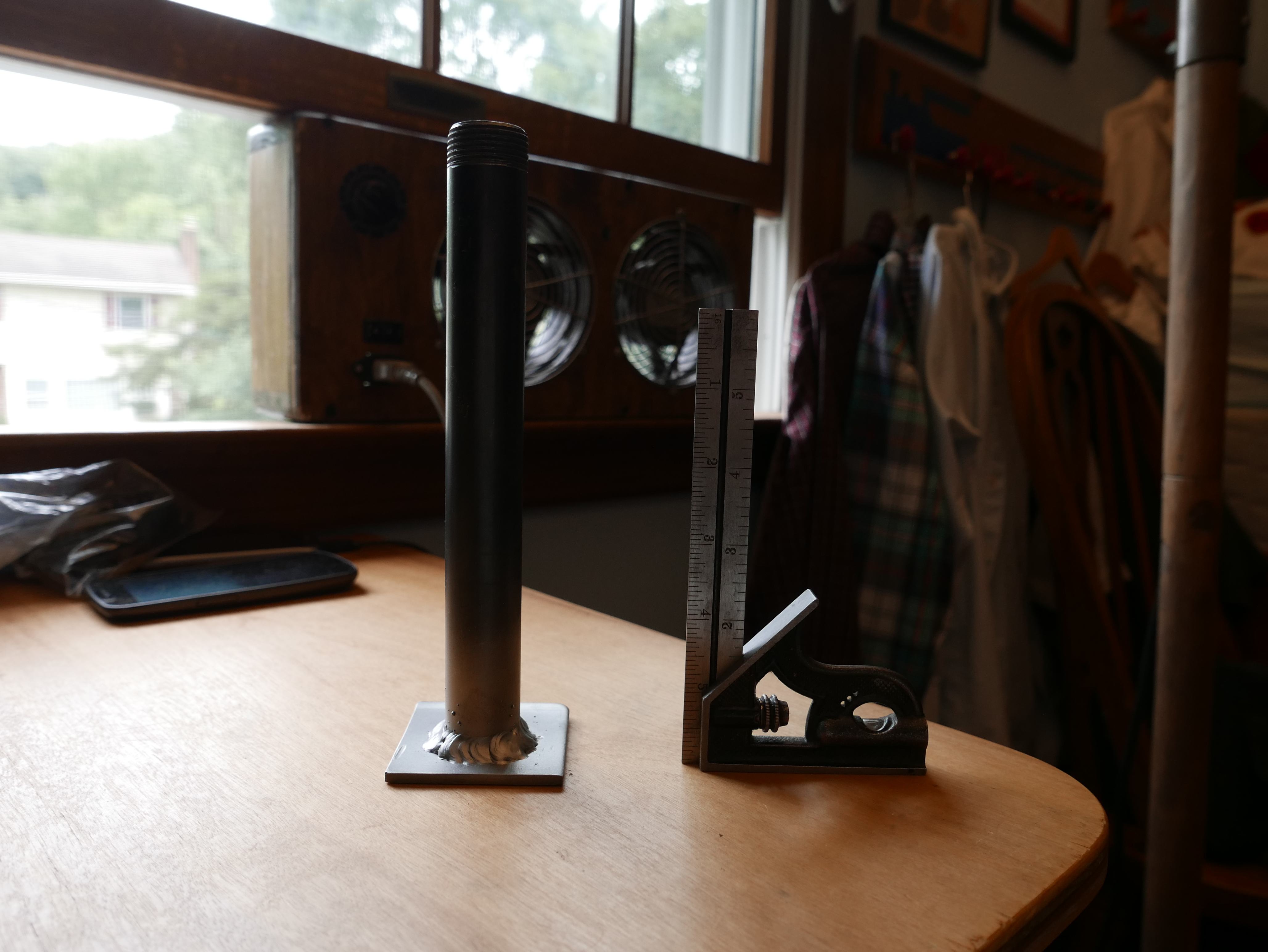
Ideally, you want to design all gimbal components as lightweight as possible to reduce the strain on the motors and the strain on the camera operator. The lighter the entire gimbal and camera rig, the longer the operator can hold it steady without the need of an external support rig. An Easyrig is a good example. In this case, I chose convenience over weight, and just made the part out of steel.
I know what you're thinking: that's a stupid idea! You should have made it out of aluminum or carbon fiber! As much as I would have loved to do that, I do not have access to a tig welder and carbon fiber would be a bear to work with for the geometry desired. I had spare steel tubing, spare plate steel and access to a mig welder, so making it out of steel was a no-brainer.
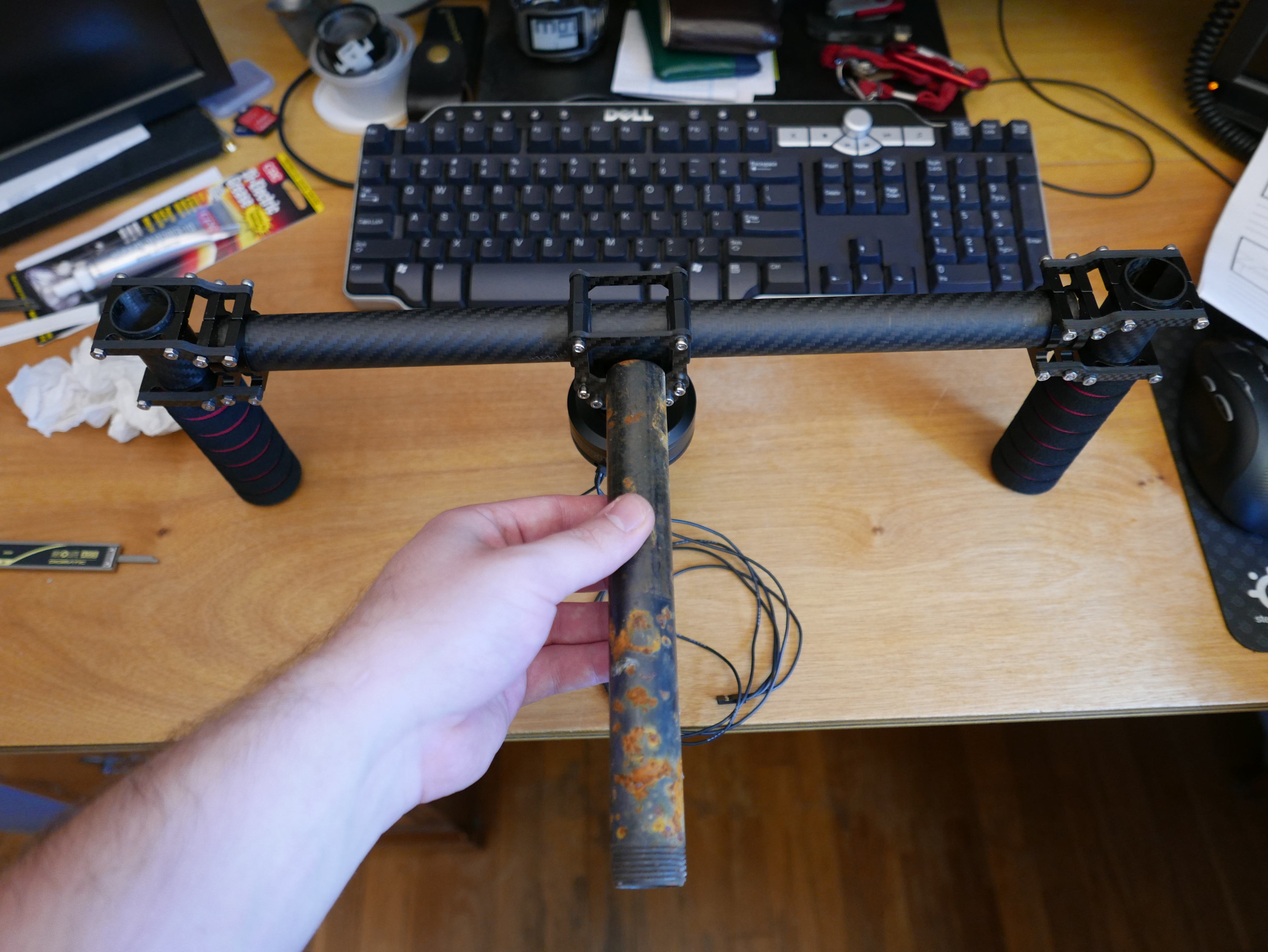
I took the bike handle bar apart again and retrieved the 6 hole patterned carbon fiber bracket. I used it as a template for cutting a matching part cut out of steel. A little bit of sanding later and I was ready to setup for welding.
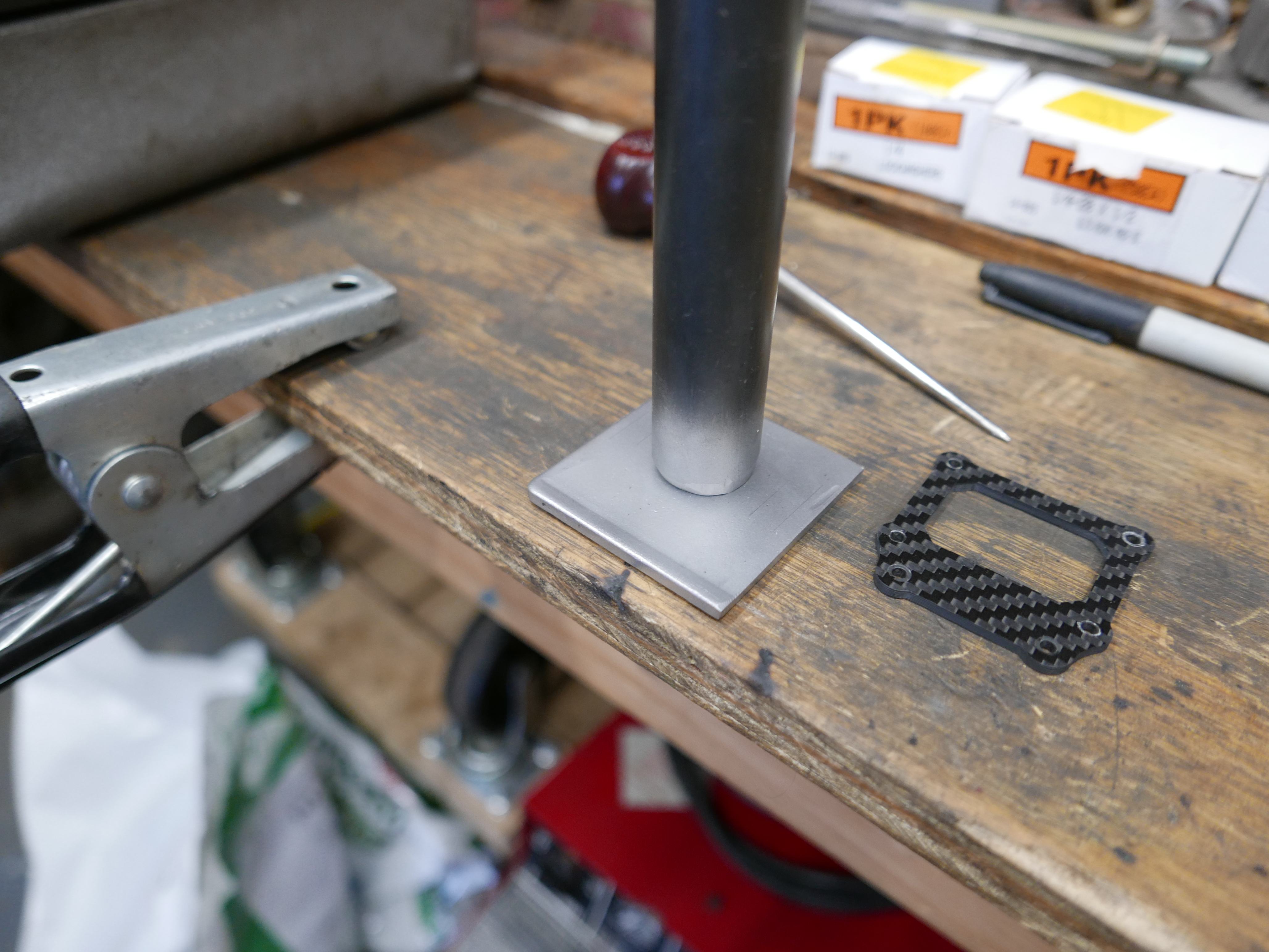
What is really neat is that I was able to have a working part within 15 minutes. The tube used was standard black iron pipe and steel brackets from an old reclining chair. My net cost was $0. That's hard to argue with!
This is of course not my welding setup as the ground lead is clamped to wood. This was just a placement shot.
The welding came out great and was relatively square. Sure I probably went a bit overkill and used thicker steel than needed, but again, hard to argue with scraps.
The tube is definitely longer than needed but I left the length to get a gauge on how long I needed it to be for the optimal top handle position.
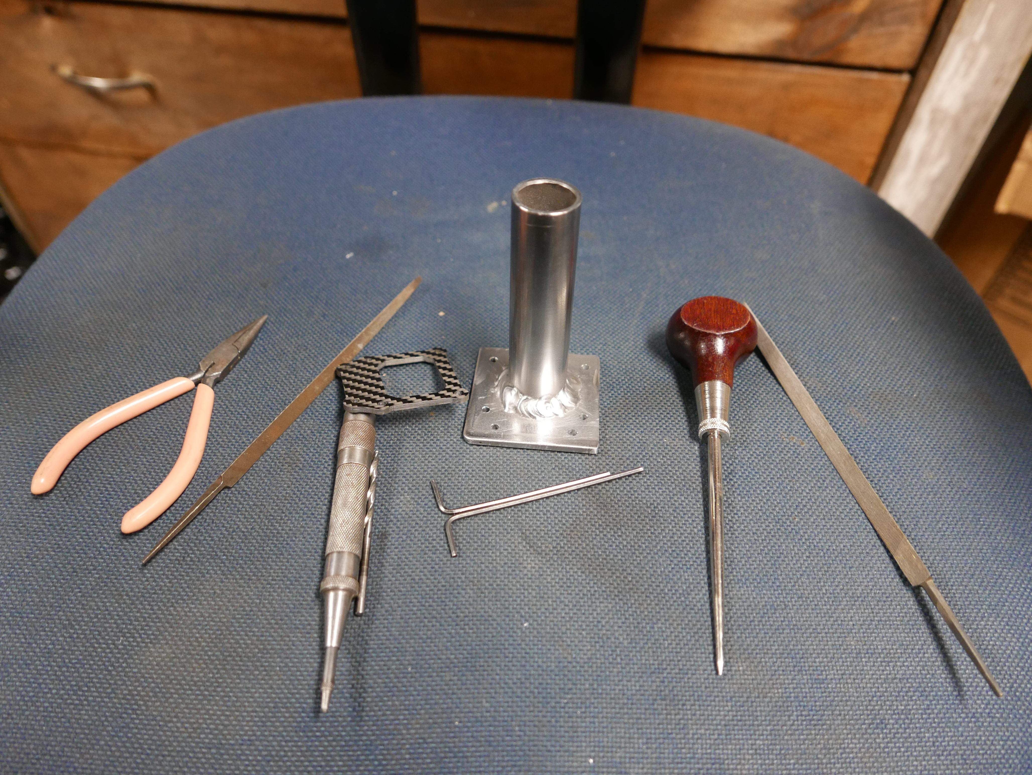
I cut the tub to length, marked the holes, and drilled them. A scribe and spring loaded center punch sure comes in handy for this type of work!
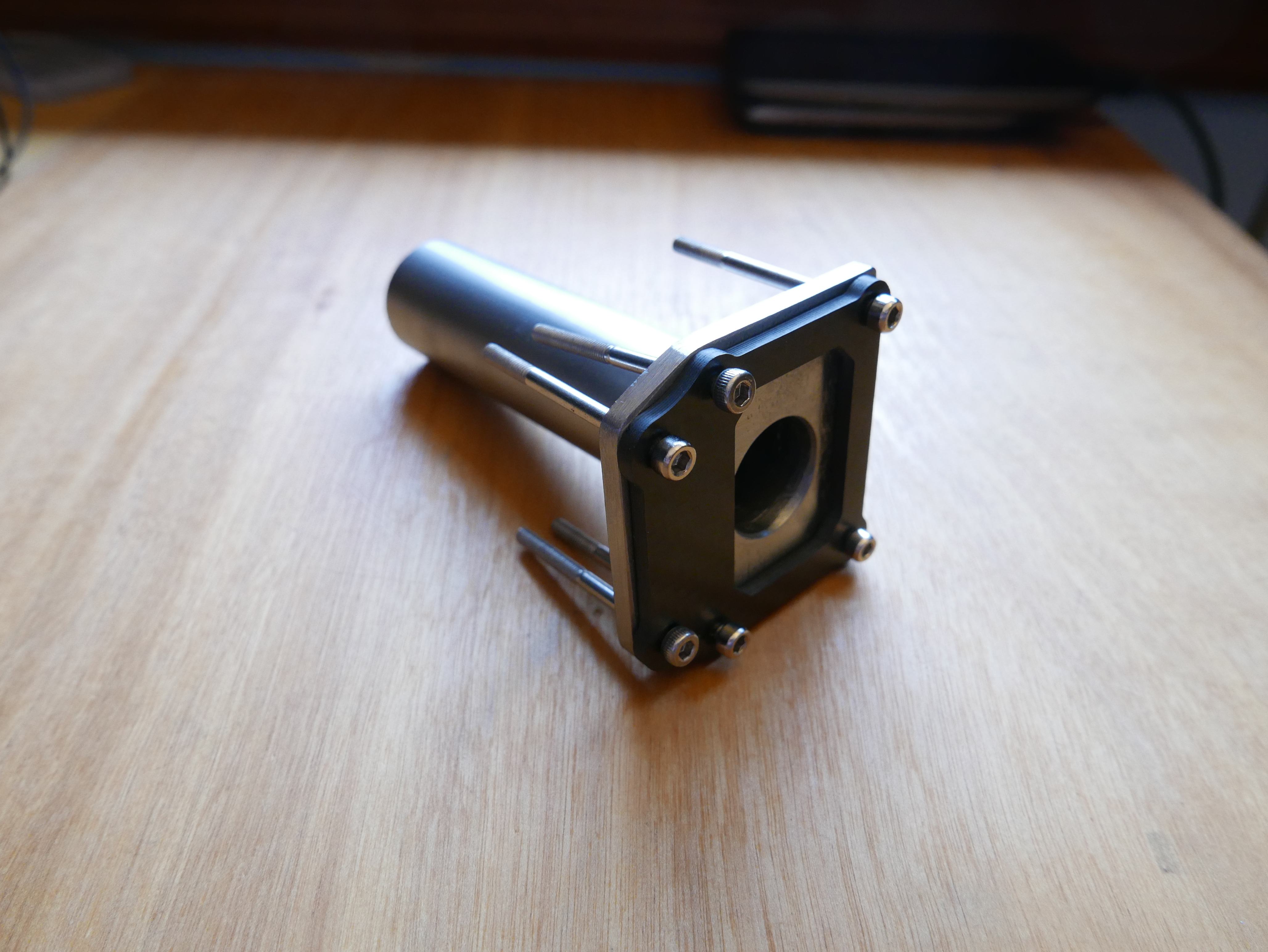
Here's the completed part. The carbon fiber counter part fits perfectly. Yes, this i completely overkill.
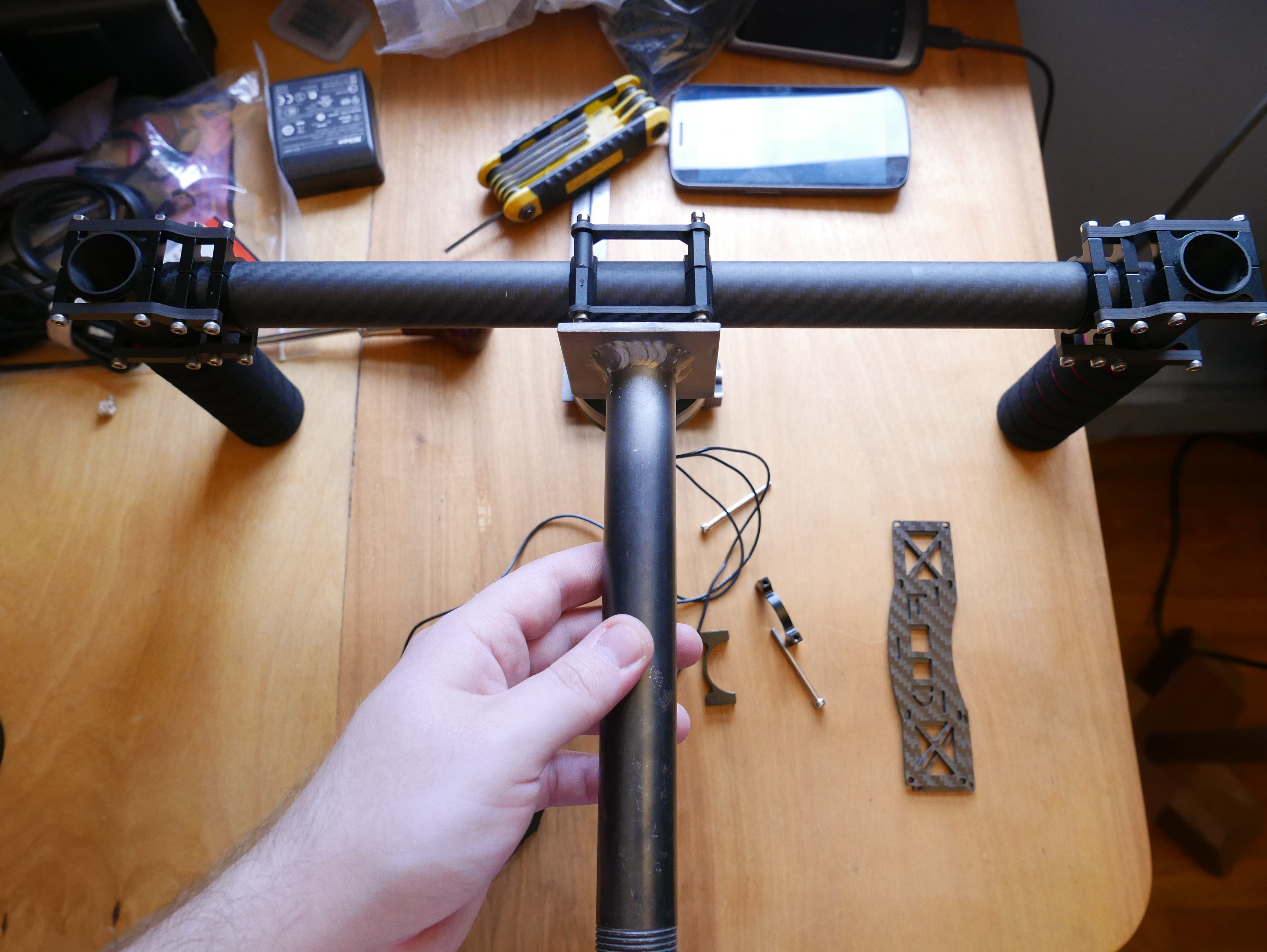
The new part works swimmingly. The top handle now completes the bike handle assembly of the gimbal. Now I just need a spare side bracket.
Where did that come from? I don't know! It sure doesn't say "Food" like the other one, but It'll do ;D
So many parts! The new components required a full reassembly of the gimbal and demanded additional table space :D
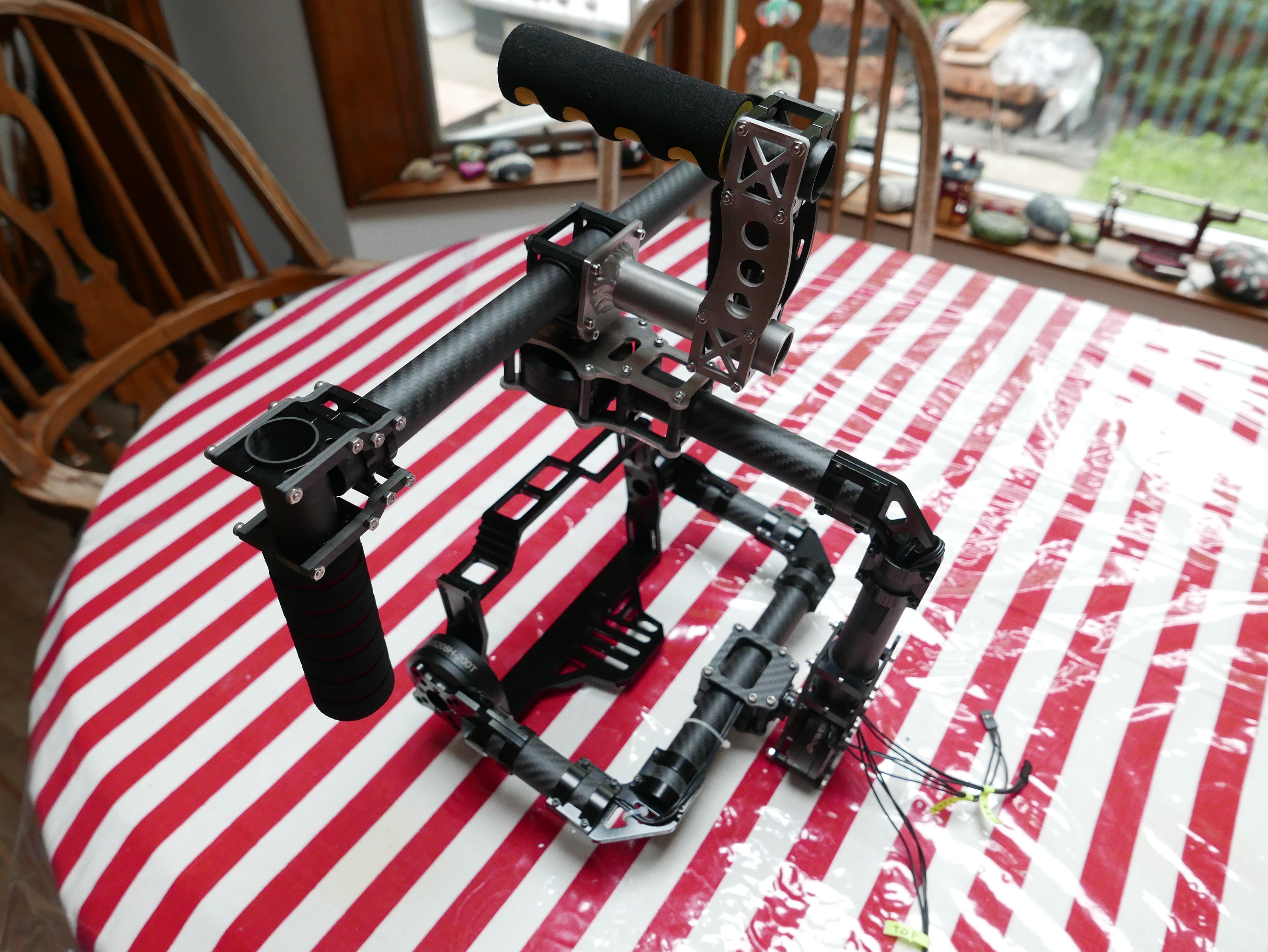
Gimbal 2.0 is finally assembled! All the new parts are installed and the gimbal is ready for further testing.
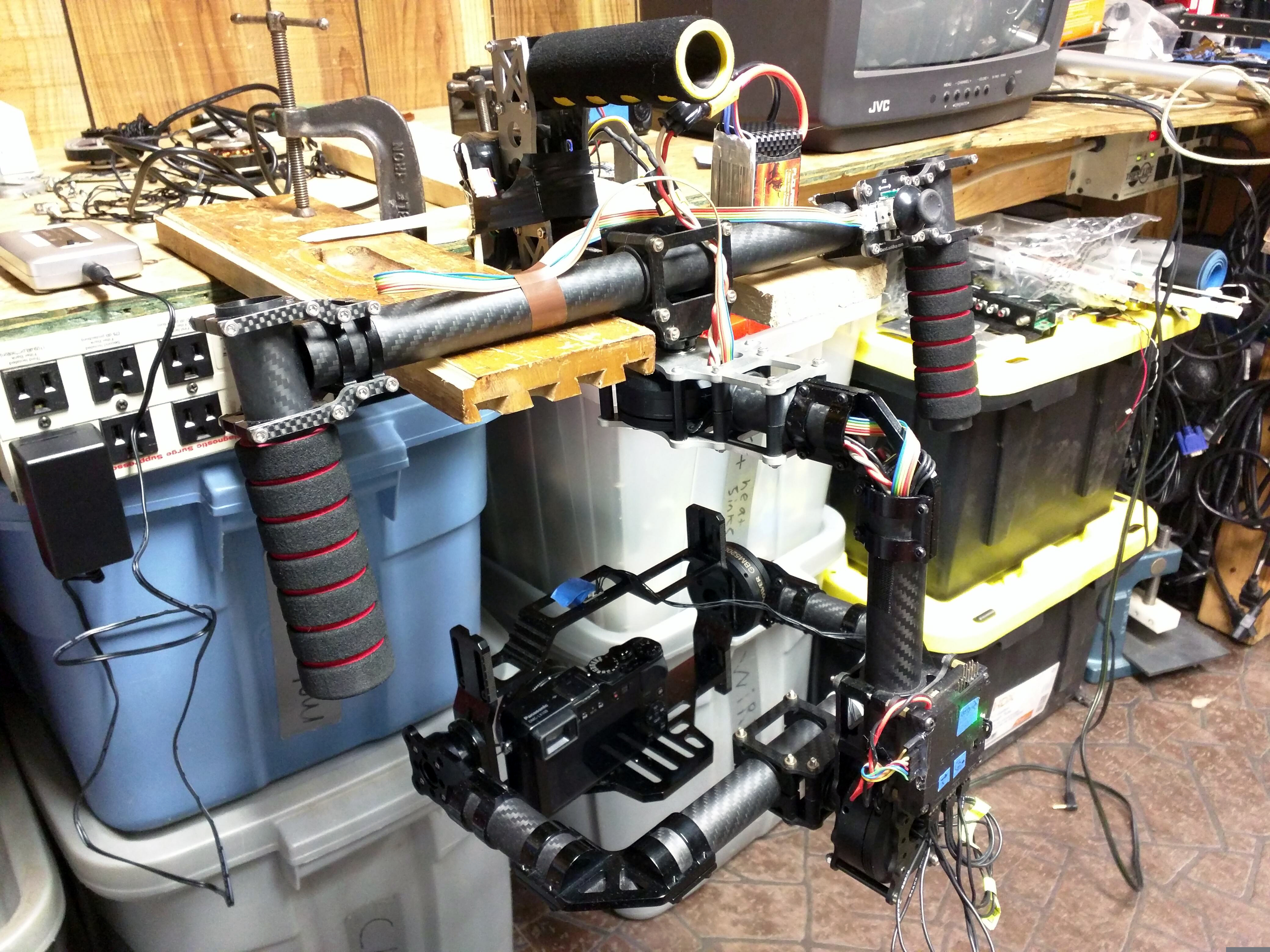
Gimbal testing commences. I needed my tripod for it's actual intended purpose so I needed to improvise a gimbal stand. Some wood scraps, clamps and a table ledge seemed to do the trick.
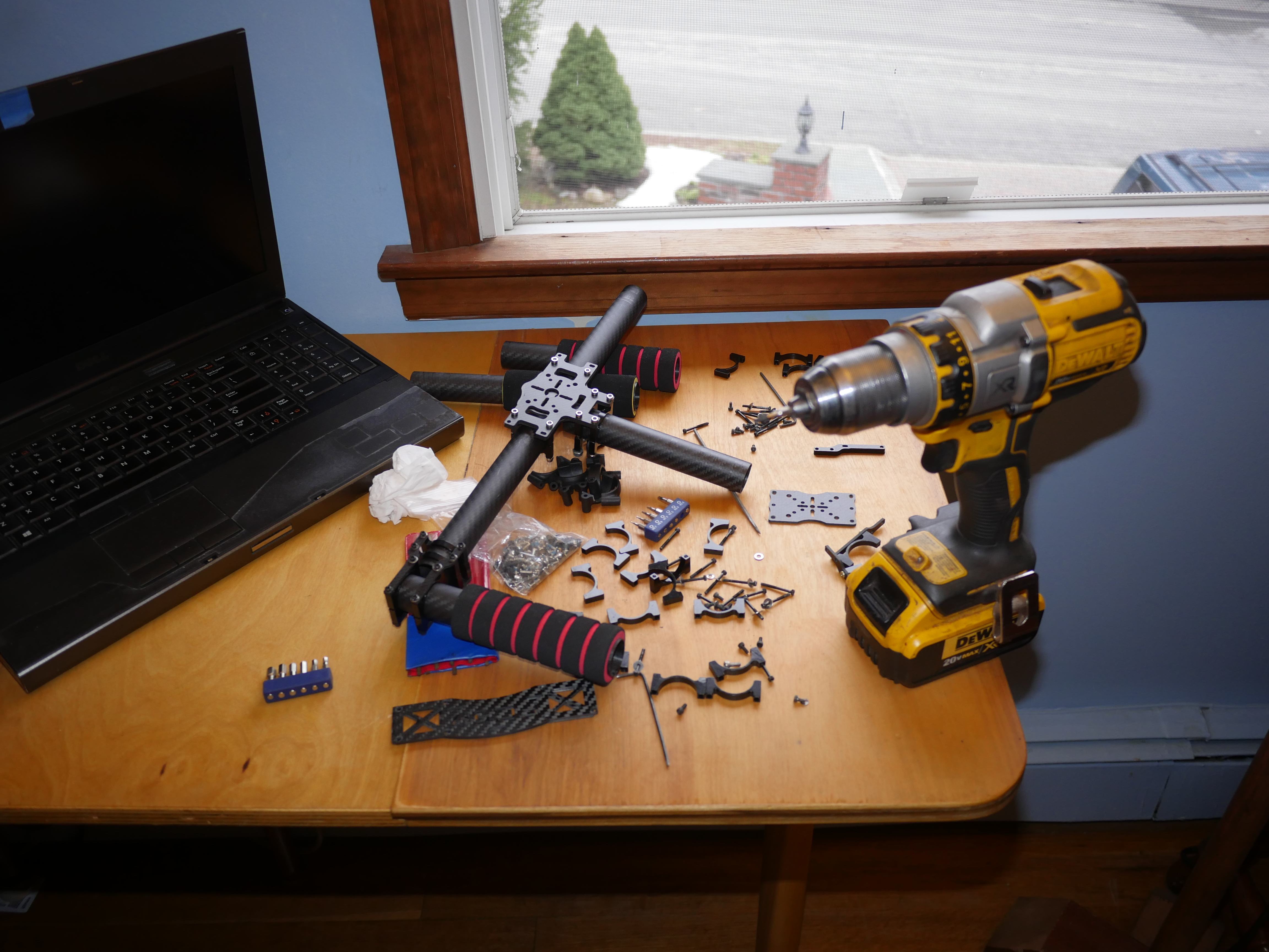
Want more? Here's a behind the scenes look at my workspace and some of the images that did not make the cut to be included in the write-up: